Position-measuring device

a technology of positioning measurement and measuring device, which is applied in the direction of measurement device, optical conversion of sensor output, instruments, etc., can solve the problems of inability to use laser interferometers as positioning measurement devices, inability to accept measured-value fluctuations on the order, and require a certain degree of technical complexity, so as to achieve precise position measurements

Active Publication Date: 2011-06-16
DR JOHANNES HEIDENHAIN GMBH
View PDF19 Cites 8 Cited by
  • Summary
  • Abstract
  • Description
  • Claims
  • Application Information

AI Technical Summary

Benefits of technology

[0009]Example embodiments of the present invention provide a position-measuring device for extremely precise position measurements, in which the simplest possible light source that allows a pulsed operation are used.
[0016]The semiconductor laser and the fiber-grating feedback device may be coupled at least partially to a temperature-setting device, via which the semiconductor laser and the fiber-grating feedback device are operable at temperatures at which the phase jitter of the displacement-dependent position signals is minimized.
[0025]Thus, particularly great coherence lengths up to more than one centimeter are available, accompanied at the same time by high power of the light source. This has advantageous consequences for the interferential scanning principle of the position-measuring device, since markedly greater path differences are possible for the partial beams of rays coming to interference. Thus, the permissible path differences may lie in the range of a few millimeters up to one centimeter. In particular, this allows position-measuring devices to have highly asymmetrical partial-beam paths, in which the light in the different partial-beam paths traverses markedly different optical path lengths. A greater acceptable path difference in the partial-beam paths also takes effect advantageously with regard to tilting tolerances. Thus, considerably greater tilting tolerances are acceptable for position-measuring devices arranged as described herein than in conventional devices.
[0026]As a further advantage, it should be mentioned that high wavelength stability of the light source results, with only low expenditure for temperature stabilization. Thus, position-measuring devices using scanning principles that are strongly wavelength-dependent are also able to be operated stably over longer periods of time. In particular, if the position-measuring device as described herein is in the form of an interferometer, high measuring accuracies may be attained in determining position.

Problems solved by technology

Given the stringent accuracy requirements then resulting, laser interferometers can no longer be used as position-measuring devices.
The refractive-index fluctuations in the ambient air, even in the case of optimal air conditioning, lead to unacceptable measured-value fluctuations on the order of several nanometers (nm) in the position determination.
In general, the described light sources satisfy the demands with respect to the coherence length, however, require a certain degree of technical complexity, especially if high optical powers are needed.

Method used


Image

  • Position-measuring device
  • Position-measuring device
  • Position-measuring device

Examples


Embodiment Construction

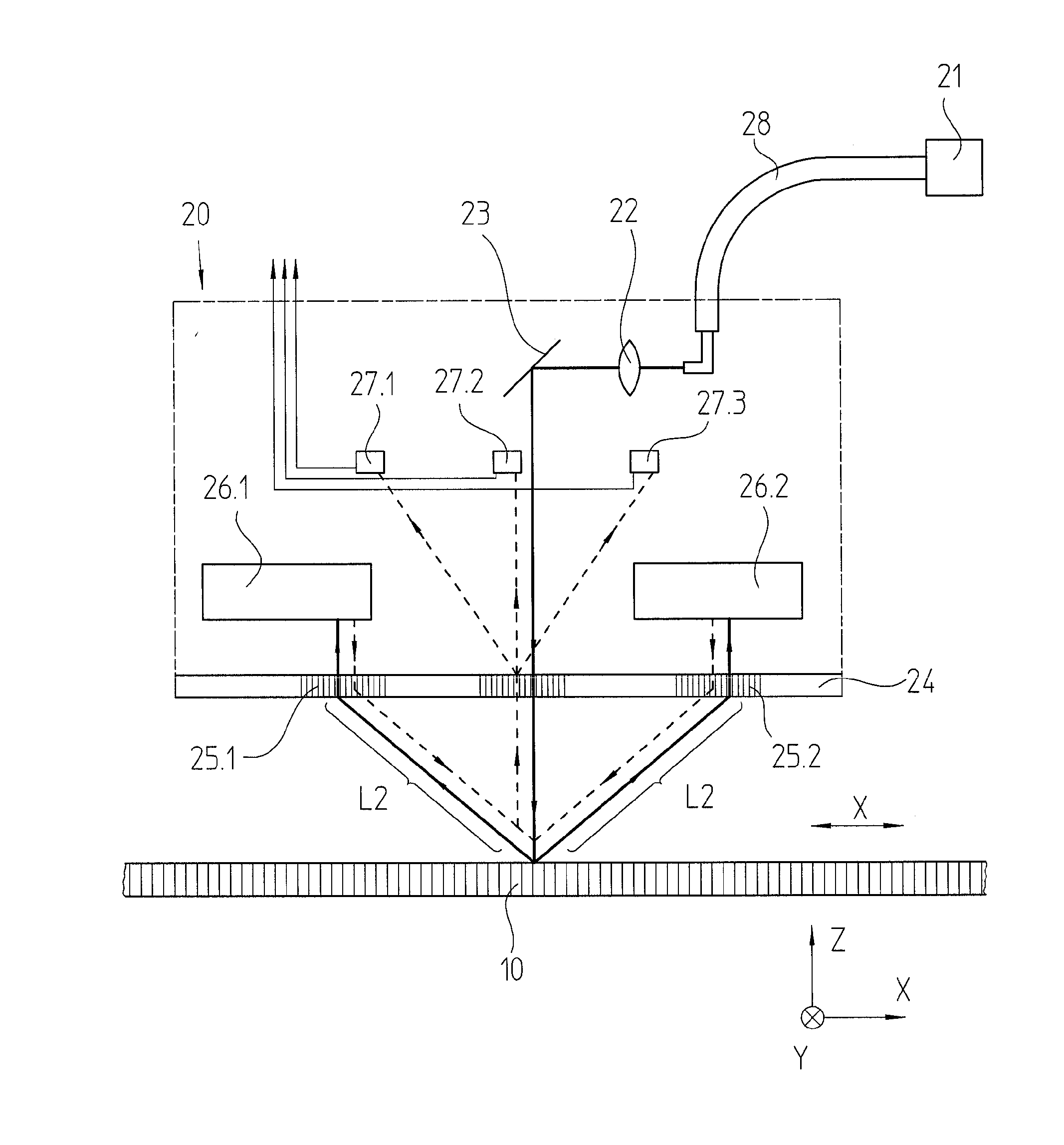
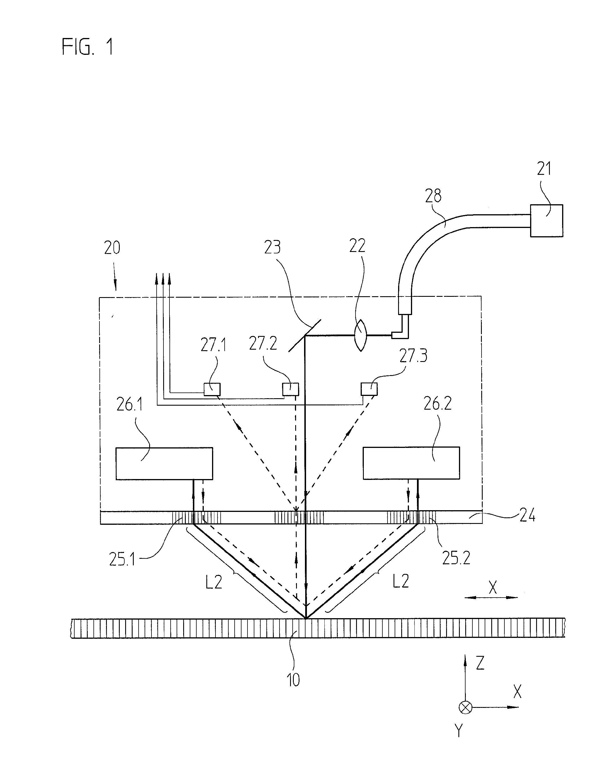
[0033]FIG. 1 schematically illustrates a position-measuring device according to an example embodiment of the present invention which has a measuring standard in the form of a grating. This exemplary embodiment is therefore constructed as a grating-based position-measuring device.

[0034]In addition to measuring standard 10, the position-measuring device includes a scanning unit 20, movable at least relatively in measuring direction x, as well as a light source 21 disposed remotely from scanning unit 20. Measuring standard 10 and scanning unit 20 are connected to two objects, whose positions are to be determined relative to each other. For example, as explained at the outset, they may be components, movable relative to each other, of a device for manufacturing semiconductor components.

[0035]In the present example, measuring standard 10 takes the form of a linear reflection measuring standard, and includes regions of different reflectivity alternating in measuring direction x.

[0036]The ...


PUM


Abstract

A position-measuring device, for ascertaining the position of two objects which are disposed in a manner allowing movement relative to each other in at least one measuring direction, includes a light source, as well as a splitting device by which a light beam, provided by the light source, is split into two or more partial beams of rays. The partial beams of rays traverse at least two partial-beam paths. Interfering partial beams of rays from the partial-beam paths strike a plurality of opto-electronic detector elements, so that displacement-dependent position signals are ascertainable via the detector elements. The light source takes the form of a semiconductor laser having a fiber-grating feedback device.

Description

CROSS-REFERENCE TO RELATED APPLICATIONS[0001]The present application claims priority to Application No. 10 2009 054 592.1, filed in the Federal Republic of Germany on Dec. 14, 2009, which is expressly incorporated herein in its entirety by reference thereto.[0002]The present application claims the benefit of U.S. Provisional Patent Application No. 61 / 286,566, filed on Dec. 15, 2009, which is expressly incorporated herein in its entirety by reference thereto.FIELD OF THE INVENTION[0003]The present invention relates to a position-measuring device.BACKGROUND INFORMATION[0004]In devices for manufacturing semiconductor components, it is necessary to precisely determine the spatial position of certain parts which are movable relative to each other, using suitable position-measuring devices. A computer-controlled sequencing control is possible in these devices based on the position information ascertained. In certain conventional methods, the position measuring necessary to this end has be...

Claims


Application Information

Patent Timeline
IPC IPC(8): G01B11/14G01B9/02
CPCG01D5/38G01D5/34746G01D5/34715
Inventor MEISSNER, MARKUS
Owner DR JOHANNES HEIDENHAIN GMBH
Why Eureka
Try Eureka