
Image capturing and transmission device and image receiving and reconstruction device

a transmission device and image technology, applied in the field of image processing devices, can solve the problems of reducing the bandwidth of color televisions, reducing the transmission area of images, and wasting a lot of time on mechanical operations, so as to reduce the traffic required for image transmission

Active Publication Date: 2011-06-09
VIVOTEK INC
View PDF4 Cites 3 Cited by
  • Summary
  • Abstract
  • Description
  • Claims
  • Application Information

AI Technical Summary

Benefits of technology

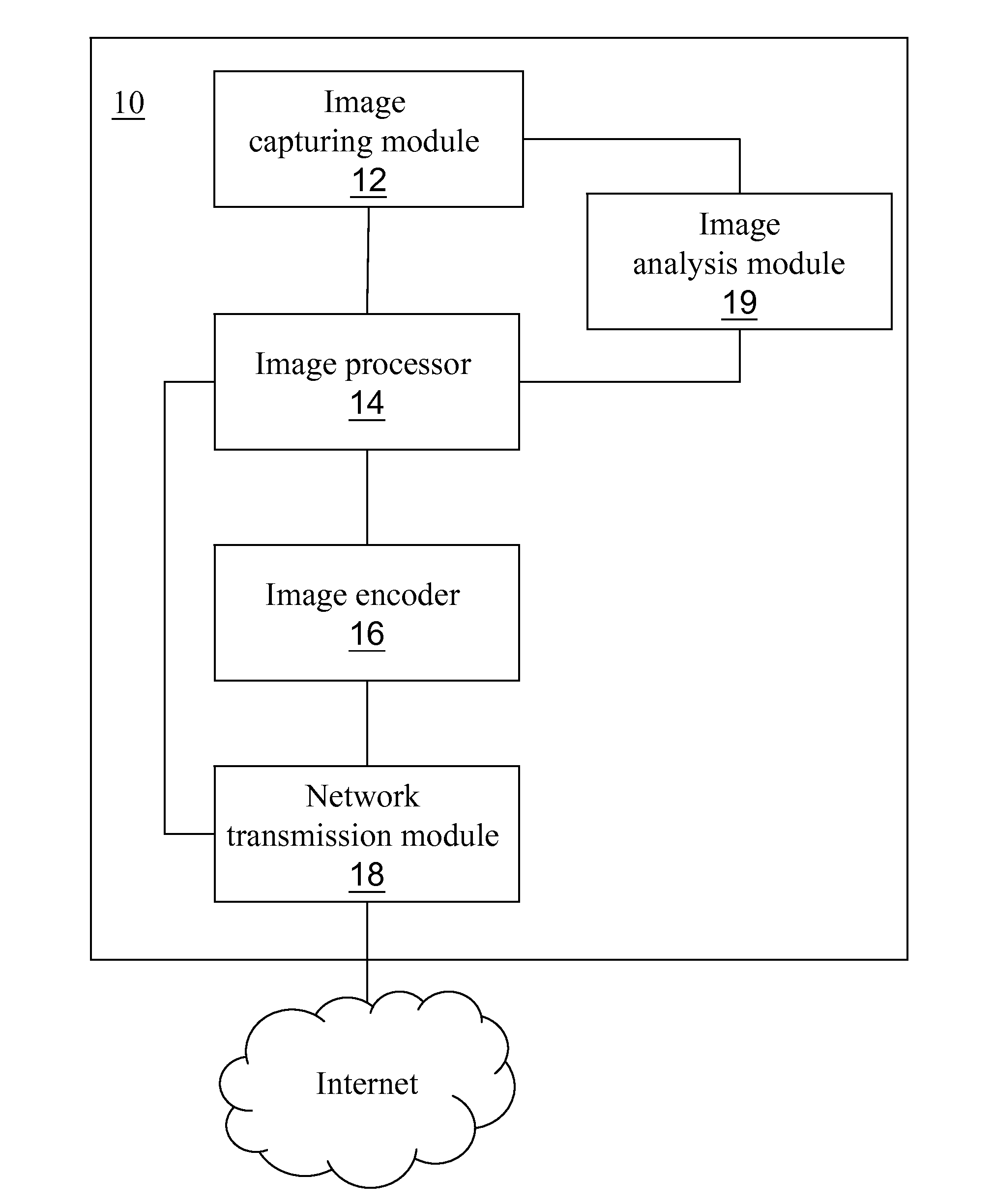
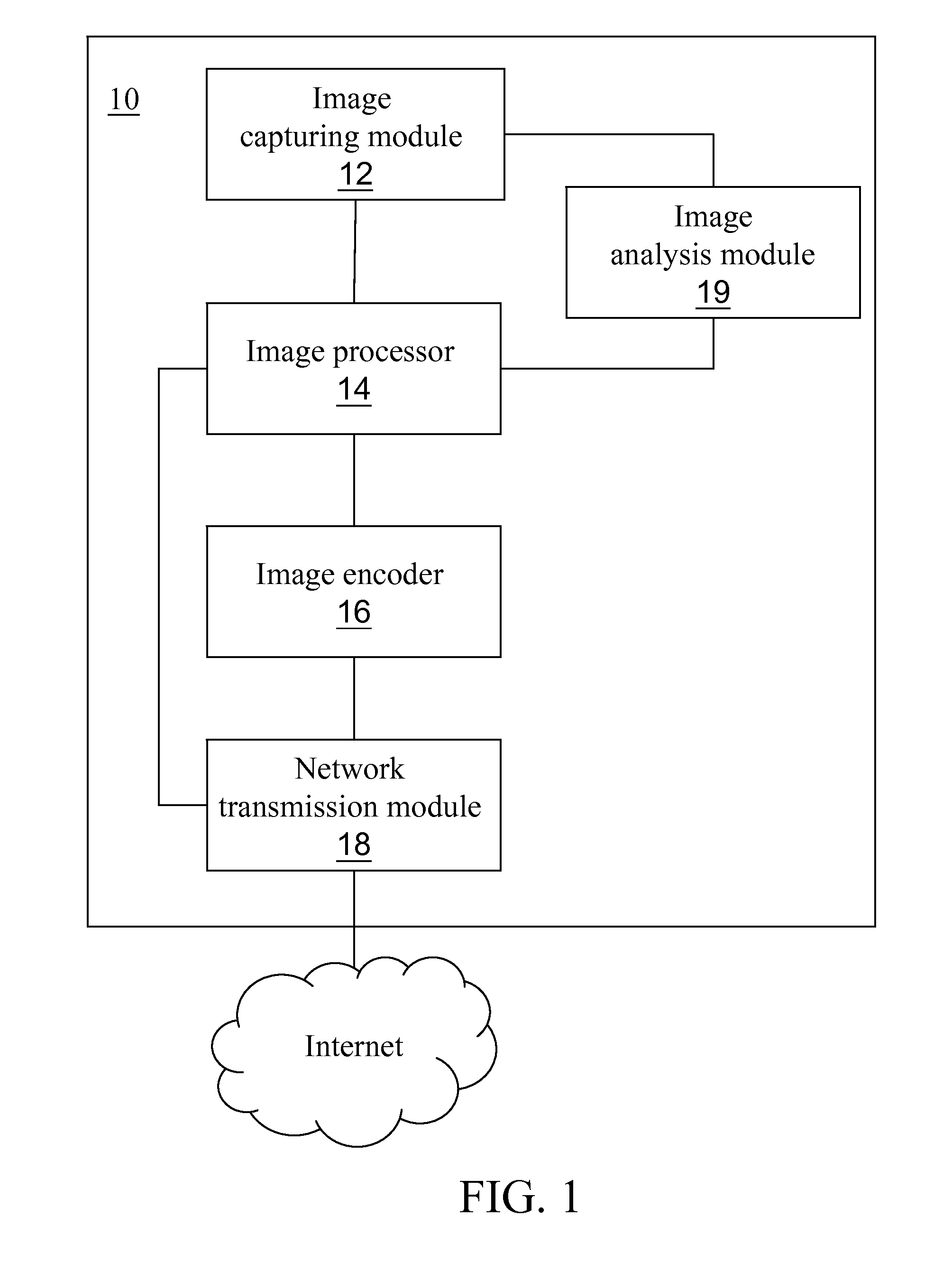
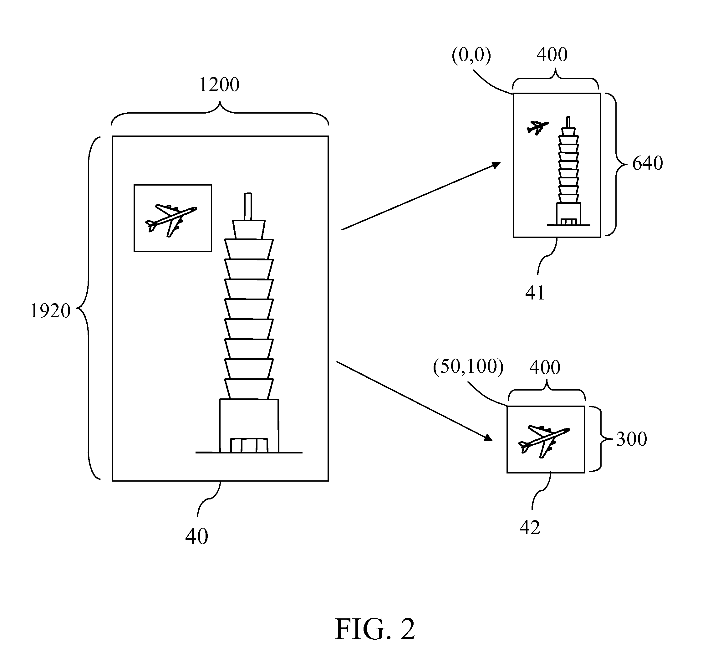
The present invention provides an image capturing and transmission device that can capture and transmit a wide-angle image of an area to be displayed. The device has an image capturing module, an image processor, an image encoder, and a network transmission module. The image processor converts the image data according to two cutting areas and shrink ratios to output two sub-images, which are then encoded and transmitted. The receiving device has a network receiving module, an image decoder, and an image reconstructor. The image decoder decodes the sub-images and outputs a restored image by converting the original area and pixel value. The image reconstructor overlaps the restored images to create a combined image with reduced traffic and improved clarity. The technical effect of this invention is that it allows for the efficient transmission and display of wide-angle images using existing networks. Additionally, users can select specific areas of interest for transmission with the same resolution to keep the frame clear and distinguishable.

Problems solved by technology

Due to the limitation of a viewing angle of a lens, the IP camera captures a limited image area.
However, in the process of panning or tiling, much time is spent on mechanical operation.
In addition, the IP camera is always damaged due to friction during the long-time rotation.
However, an image shot by the wide-angle lens is not as clear as that shot by a conventional zoom lens.

Method used


Image

  • Image capturing and transmission device and image receiving and reconstruction device
  • Image capturing and transmission device and image receiving and reconstruction device
  • Image capturing and transmission device and image receiving and reconstruction device

Examples


Embodiment Construction

[0026]The detailed features and advantages of the present invention are described below in great detail through the following embodiments, the content of the detailed description is sufficient for those skilled in the art to understand the technical content of the present invention and to implement the present invention there accordingly. Based upon the content of the specification, the claims, and the drawings, those skilled in the art can easily understand the relevant objectives and advantages of the present invention. The following embodiments are intended to describe the present invention in further detail, but not intended to limit the scope of the present invention in any way.

[0027]FIG. 1 is a system block diagram of an image capturing and transmission device according to the present invention. Referring to FIG. 1, the image capturing and transmission device 10 comprises an image capturing module 12, an image processor 14, an image encoder 16, and a network transmission modul...


PUM


Abstract

An image capturing and transmission device includes an image capturing module, an image processor, an image encoder, and a network transmission module. The image capturing module is used for capturing a scene of an area to be displayed and outputting image data. The image processor converts the image data according to a first and a second cutting areas and a first and a second shrink ratio values, and outputs a first and a second sub-images. The first cutting area includes the second cutting area, and the first shrink ratio value is greater than the second shrink ratio value. The image encoder encodes the first and the second sub-images according to first and second encoding information, and outputs a first and a second streaming images. The network transmission module is used for transmitting the first and the second streaming images.

Description

CROSS-REFERENCE TO RELATED APPLICATIONS[0001]This non-provisional application claims priority under 35 U.S.C. §119(a) on Patent Application No(s). 098141633 filed in Taiwan, R.O.C. on Dec. 4, 2009, the entire contents of which are hereby incorporated by reference.BACKGROUND[0002]1. Field of Invention[0003]The present invention relates to an image processing device, and more particularly to an image capturing and transmission device and an image receiving and reconstruction device.[0004]2. Related Art[0005]With the rapid development of the network technology, new products derived from different application networks emerge accordingly. One technology for application among them is IP camera.[0006]Appearing in about 1998, the IP camera makes use of advanced multimedia video and image compression technologies in combination with the advantage of being boundless of the Internet, so that a user can view real-time digital high-definition images transmitted from an IP camera installed at a r...

Claims


Application Information

Patent Timeline
Patent Type & Authority Applications(United States)
IPC IPC(8): H04N7/50H04N5/225
CPCH04N5/23206H04N5/23229H04N19/172H04N19/162H04N19/12H04N19/164H04N19/61H04N23/661H04N23/80
Inventor WU, JEN CHIH
Owner VIVOTEK INC
Learn More