
Thermal Stress Indicator

Active Publication Date: 2011-06-09
KIMBERLY-CLARK WORLDWIDE INC
View PDF14 Cites 37 Cited by
  • Summary
  • Abstract
  • Description
  • Claims
  • Application Information

AI Technical Summary

Benefits of technology

[0022]By providing the thermal stress monitoring device of the present invention, an effective device to monitor and warn a user of the possibility of thermal stress is about to occur or could occur is provided.

Problems solved by technology

However, increased workload compounded by environmental factors such as air temperature, radiant heat sources, and humidity may stress the body's ability to safely regulate its internal temperature.
Heat stress is a potentially dangerous build up of heat within a body and is a hazard faced by many workers and athletes.
The use of necessary protective apparel when working in hot environments puts such workers at an increased risk of heat stress.
On the other end of the temperature spectrum, workers in cold environments are at risk of an unsafe decrease in the body core temperature known as hypothermia.
However, such measurements and use of reference materials is not necessarily convenient or practical in the average dynamic work environment.
Similarly, the onset of hypothermia occurs when the body core temperature drops below 35° C. Having a core body temperature outside the range of about 35° C. to about 38° C. can result in the failure of various systems of the body and may ultimately result in death.
While such invasive measurement methods work well for patients in a controlled environment, such techniques are not feasible for use with workers in a comparatively uncontrolled working environment or for an athlete undertaking their particular activity.
Such invasive methods are even less practical in situations where continuous monitoring the core temperature of such a worker or athlete is desired.
However, such estimates of core temperature are user-specific and are not practical for the working environs, and under the conditions, in which a worker or athlete may be at risk for thermal stress and would particularly benefit from such monitoring.
Thus, estimates of core body temperature may become more inaccurate in situations of rapid temperature change and increased subject perspiration; the very situations in which such thermal stress monitoring is most needed.

Method used


Image

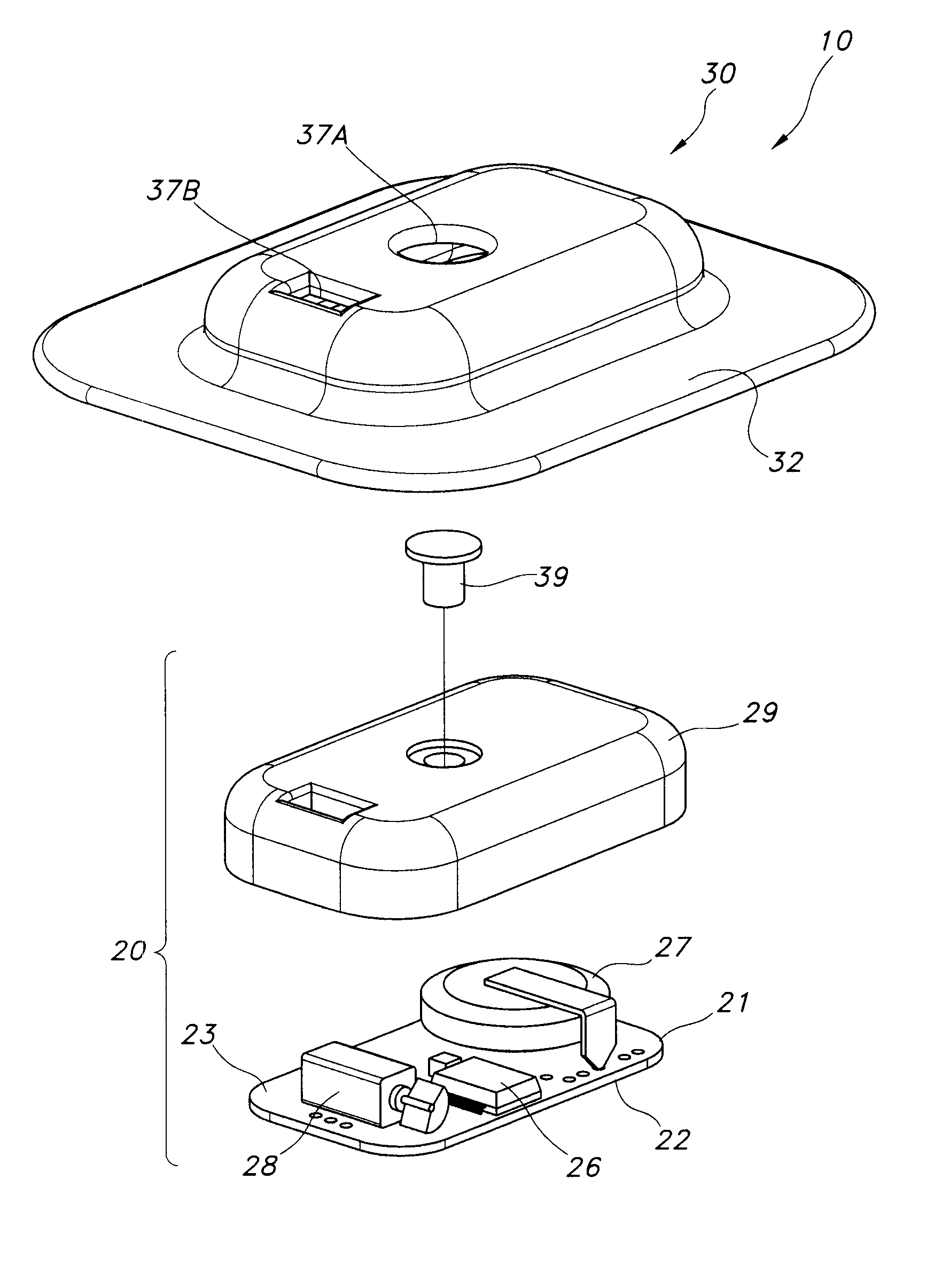
  • Thermal Stress Indicator
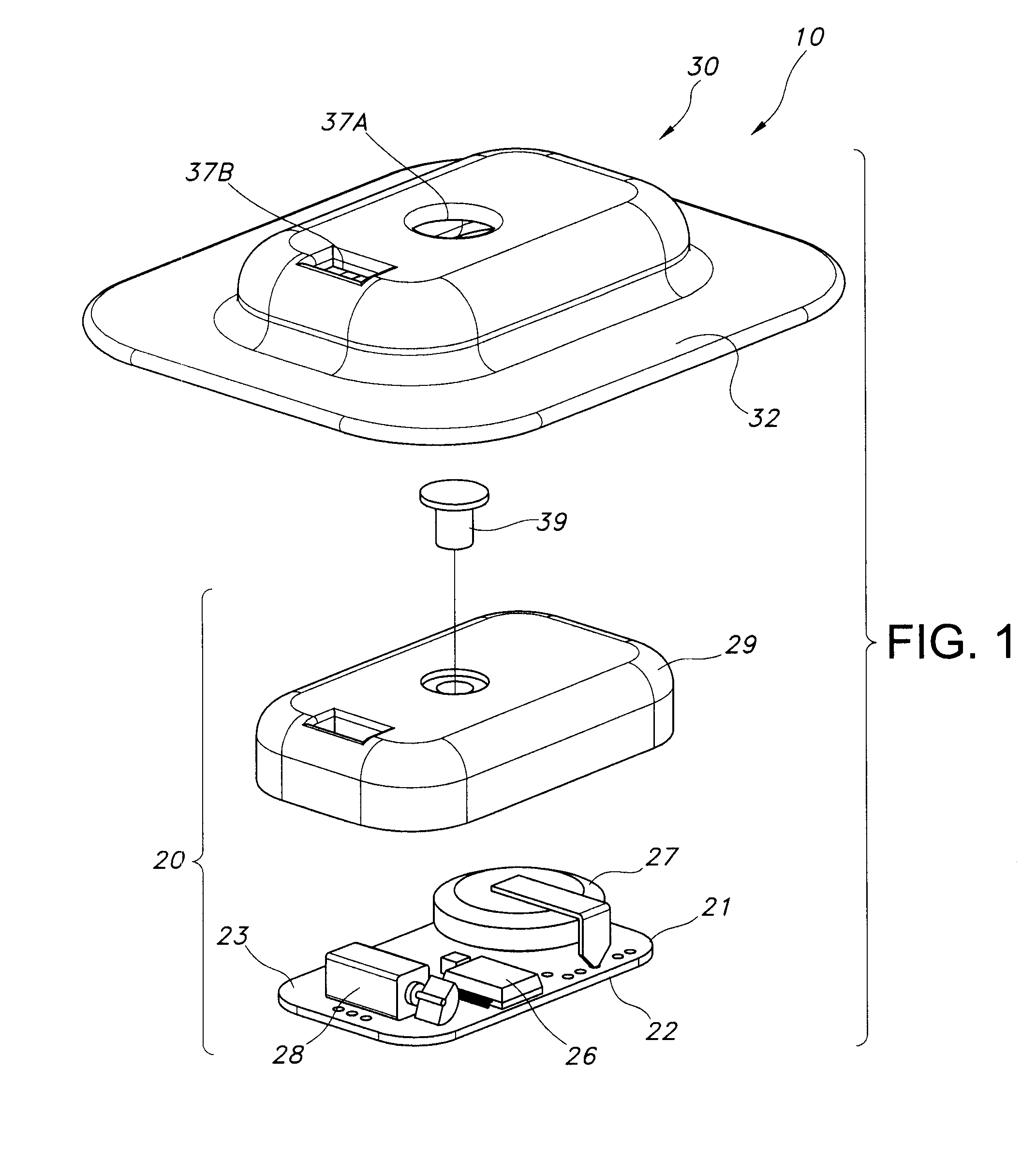
  • Thermal Stress Indicator
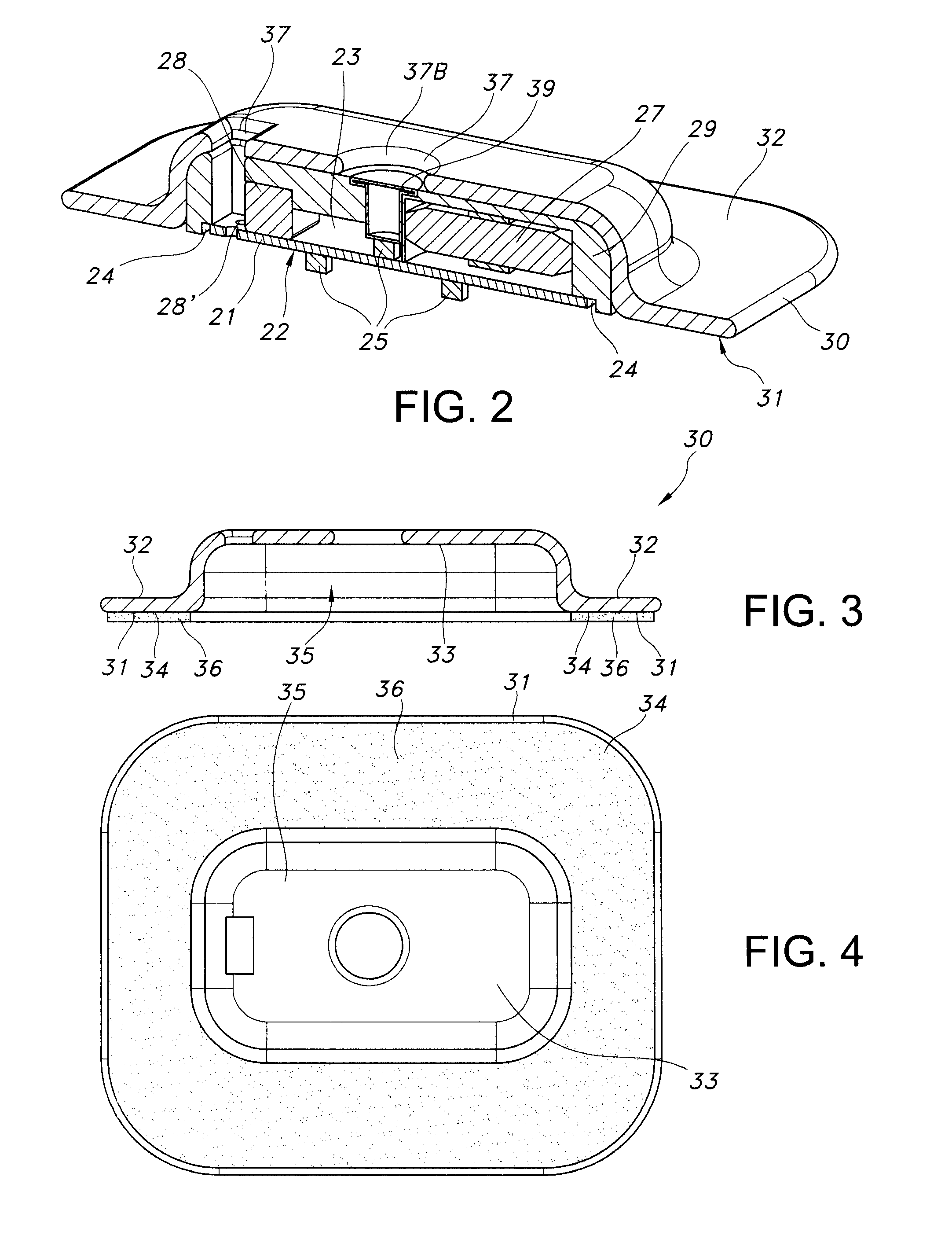
  • Thermal Stress Indicator

Examples


Embodiment Construction

[0045]The present invention provides a non-invasive monitoring device to check the possibility of thermal stress of a user. In addition, the present invention provides a method to monitor thermal stress of a user of the device of the present invention. The user may use such a device while in environments they wish to work in, engage in athletic activities, or otherwise be present. Such a device and method of monitoring may be especially useful in environments and conditions where a user may be at higher risk for thermal stress. The materials and configuration of the device, and its method of use, are uniquely designed to more accurately account for the conditions in which thermal stress may be a danger. For example, such a device may be useful in helping firefighters monitor themselves for heat stress when fighting a blaze while wearing full-protective gear. Similarly, such a device may be useful in helping athletes to monitor themselves for heat stress while exerting themselves on ...


PUM


Abstract

The present invention provides a device for non-invasive monitoring thermal stress of a user. The device is capable of monitoring the internal body temperature and changes in the internal body temperature of a user. Also, the device is capable of alerting a user when the user is in danger of thermal stress.

Description

FIELD OF THE INVENTION[0001]The present invention generally relates to a thermal stress indicator and the method of using the thermal stress indicator.BACKGROUND[0002]Under normal circumstances the human body is exceptionally efficient at regulating a constant internal temperature. However, increased workload compounded by environmental factors such as air temperature, radiant heat sources, and humidity may stress the body's ability to safely regulate its internal temperature. Heat stress is a potentially dangerous build up of heat within a body and is a hazard faced by many workers and athletes. The use of necessary protective apparel when working in hot environments puts such workers at an increased risk of heat stress. On the other end of the temperature spectrum, workers in cold environments are at risk of an unsafe decrease in the body core temperature known as hypothermia.[0003]The current industry practice to limit the potential hazard of thermal stress includes controlling w...

Claims


Application Information

Patent Timeline
IPC IPC(8): G08B17/00
CPCA61B5/0008A61B5/01A61B5/6814A61B5/6833A61B2560/0412G01K3/10G01K7/427G01K13/002A61B2562/0271G01K13/20
Inventor RANGANATHAN, SRIDHARBAKER, ANDREW THOMASHELLER, JEFFREY
Owner KIMBERLY-CLARK WORLDWIDE INC
Learn More