Method for making deicing system on a nacelle panel

a deicing system and nacelle technology, applied in the direction of electrical equipment, air transportation, jet propulsion plants, etc., can solve the problems of significant risk of piercing the resistive elements, and affecting the deicing effect of the nacelle panel, so as to achieve convenient implementation and efficient deicing

Inactive Publication Date: 2011-06-09
SAFRAN NACELLES
View PDF7 Cites 10 Cited by
  • Summary
  • Abstract
  • Description
  • Claims
  • Application Information

AI Technical Summary

Benefits of technology

[0009]One aim of the present invention is to provide a nacelle panel including at least one hole and an efficient deicing system that is easy to implement and ensures ongoing deicing.

Problems solved by technology

The presence of ice or frost modifies the aerodynamic properties, which disrupts the conveyance of the air towards the fan.
However, the deicing system is generally not visible during the piercing, which causes a significant risk of piercing the resistive elements.
Such damage, which is difficult to detect, has the consequence of breaking the continuity of the deicing performance.

Method used


Image

  • Method for making deicing system on a nacelle panel
  • Method for making deicing system on a nacelle panel
  • Method for making deicing system on a nacelle panel

Examples


Embodiment Construction

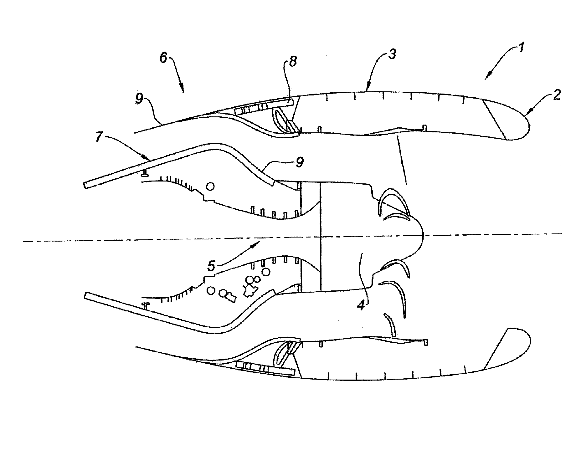
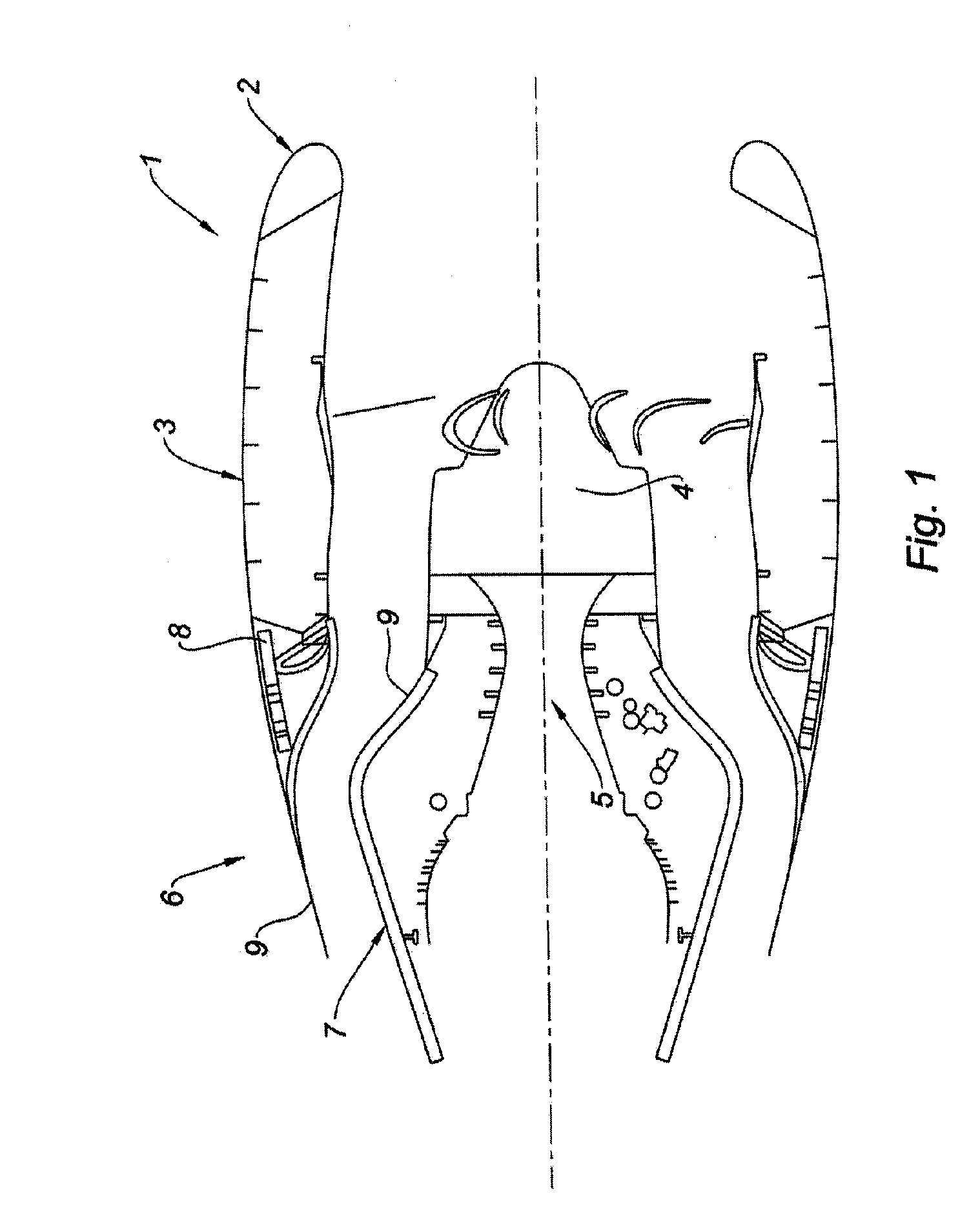
[0037]As shown in FIG. 1, a nacelle 1 according to the invention comprises an air intake lip 2, a middle structure 3 surrounding a fan 4 of a turboshaft engine 5 and a downstream assembly 6. The downstream assembly 6 is made up of an inner fixed structure 7 (IFS) surrounding the upstream portion of the turboshaft engine 5, an outer fixed structure 8 (OFS) and a mobile cowl 9 including thrust reverser means.

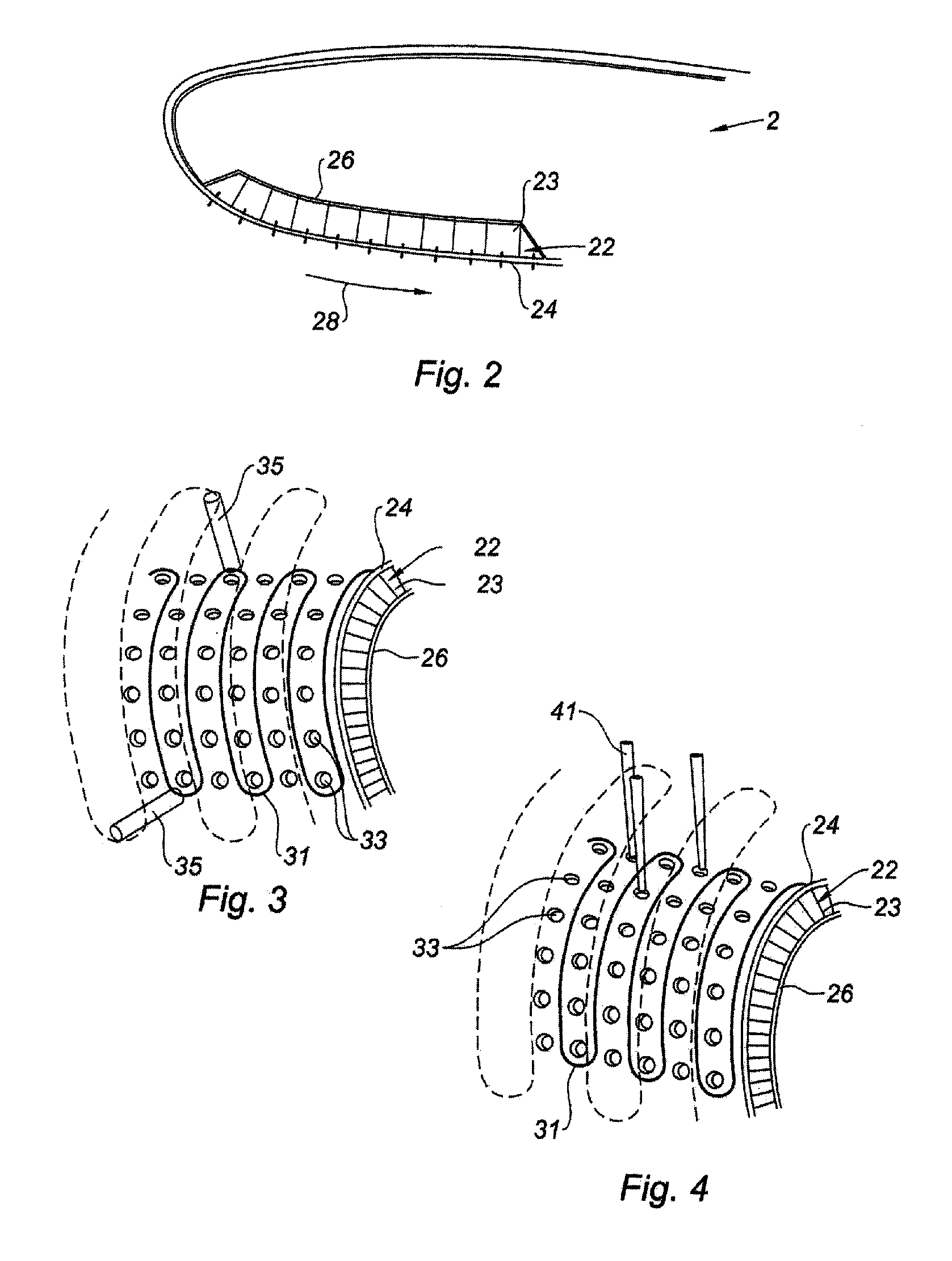
[0038]The nacelle 1 according to the invention has elements, including the air intake lip 2, capable of being covered with frost or ice, which is damaging to the performance of the aircraft. The deicing system of the present invention makes it possible to eliminate frost or said ice on these elements and in particular on the air intake lip 2. Said elements can have surfaces of all shapes. Examples include the presence of deicing around the access panel fastenings or the presence of deicing around the drain hole of elements of the nacelle 1.

[0039]According to the embodiment illustr...


PUM

PropertyMeasurementUnit
thicknessaaaaaaaaaa
temperatureaaaaaaaaaa
aerodynamic propertiesaaaaaaaaaa

Abstract

The invention relates to a method for making a deicing system on a panel (22) of a nacelle comprising an outer skin (24) having at least one hole and an inner skin (26), characterized in that it comprises the following steps: A. a grid of resistive elements is positioned on the outer skin (24) with respect to the hole(s) by a positioning means; B. the grid of resistive elements is applied by an application means to the location determined in step A to form the deicing system; C. a surface coating is applied to the resulting deicing system. The present invention also relates to an air inlet lip and to a nacelle comprising a deicing system produced by such method.

Description

TECHNICAL FIELD[0001]The invention relates to a method for making a deicing system on a nacelle panel.[0002]The invention also relates to an air intake lip as well as a nacelle for a turboshaft engine.BACKGROUND[0003]An airplane is propelled by one or several propulsion assemblies each comprising a turboshaft engine housed in a tubular nacelle. Each propulsion assembly is attached to an aircraft by a mast situated under a wing or at the fuselage.[0004]A nacelle generally has a structure comprising an air intake upstream of the engine and a middle section capable of surrounding a fan of the turboshaft engine, a downstream section housing thrust reverser means and able to surround the combustion chamber of the turboshaft engine. The nacelle ends with a jet nozzle whereof the outlet is situated downstream of the turboshaft engine.[0005]The air intake comprises, on one hand, an air intake lip adapted to allow optimal collection towards the turboshaft engine of the air necessary to suppl...

Claims


Application Information

Patent Timeline
Patent Type & Authority Applications(United States)
IPC IPC(8): B64D15/12H05B3/00
CPCB64D29/00B64D33/02B64D2033/0206B64D2033/0233B64D2033/0286F02C7/045Y10T29/49083H05B3/28Y02T50/67Y02T50/672F05D2250/191F05D2250/283F02C7/047Y02T50/60Y10T29/4932Y10T29/49622Y10T29/49888
Inventor VAUCHEL, GUY BERNARDGEROME, MARCLEMAINS, LAURENCE
Owner SAFRAN NACELLES
Why Eureka
Try Eureka