
Connector clip

Active Publication Date: 2011-06-09
USG INTERIORS LLC
View PDF13 Cites 5 Cited by
  • Summary
  • Abstract
  • Description
  • Claims
  • Application Information

AI Technical Summary

Benefits of technology

[0003]The invention provides an end connector clip for suspended ceiling grid runners with improved clip-to-clip locking action. The improved locking function, in accordance with the invention, is achieved by orienting the locking surfaces with an angle relative to the plane of the clip body proper greater than what results from conventional practice. A preferred manner of forming the inventive locking surfaces is by increasing the clearance between the punch and die elements that create the locking surfaces. This technique, it has been found, develops an orientation of a locking surface that, in use, counteracts forces that tend to laterally separate mating locking surfaces of a pair of coupled clips which otherwise could result in a major loss of retention force. Ideally, the inventive technique is applied to both a locking projection and a projection receiving area of the clip.

Problems solved by technology

This technique, it has been found, develops an orientation of a locking surface that, in use, counteracts forces that tend to laterally separate mating locking surfaces of a pair of coupled clips which otherwise could result in a major loss of retention force.

Method used


Image

  • Connector clip
  • Connector clip
  • Connector clip

Examples


Embodiment Construction

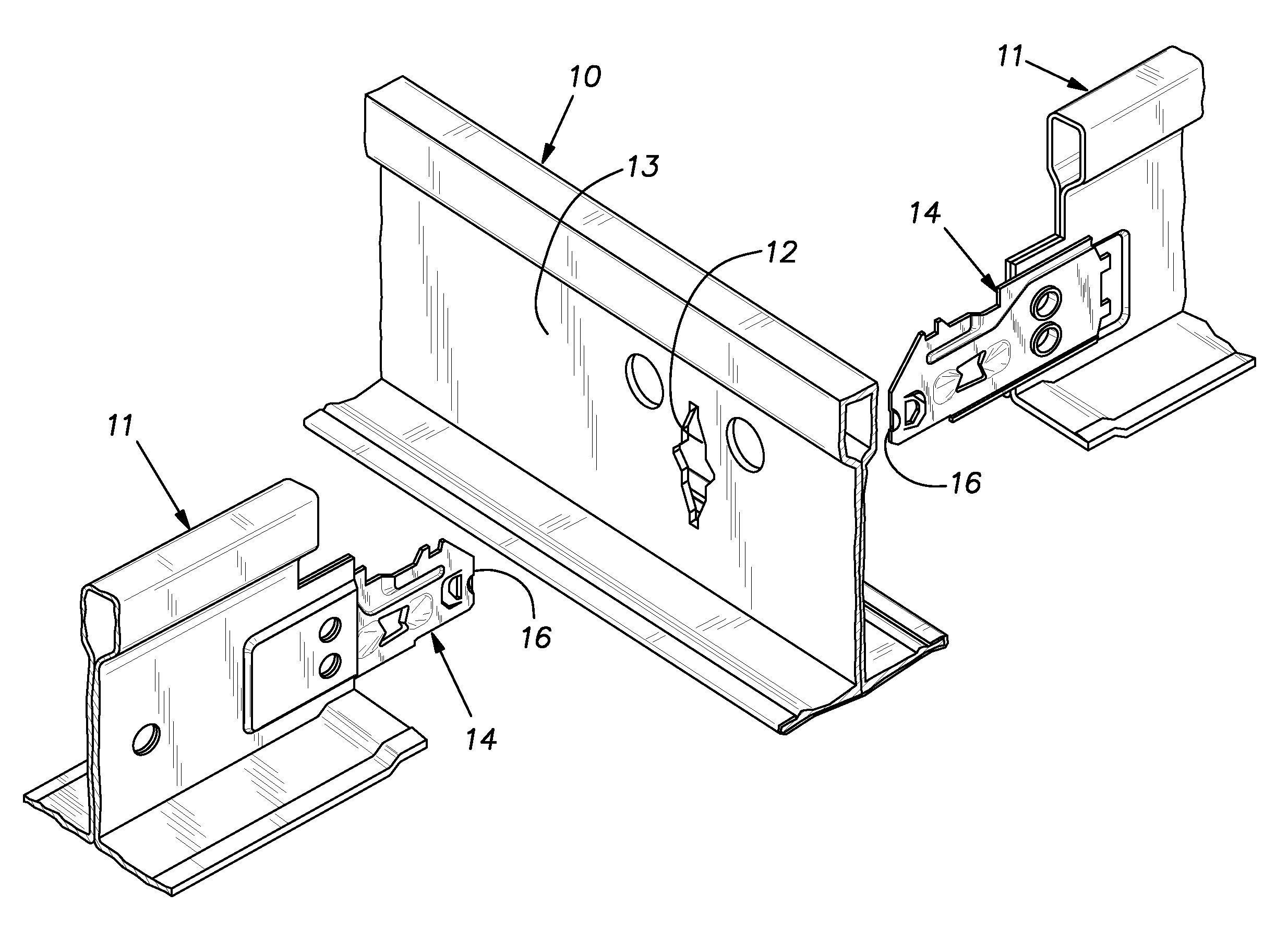
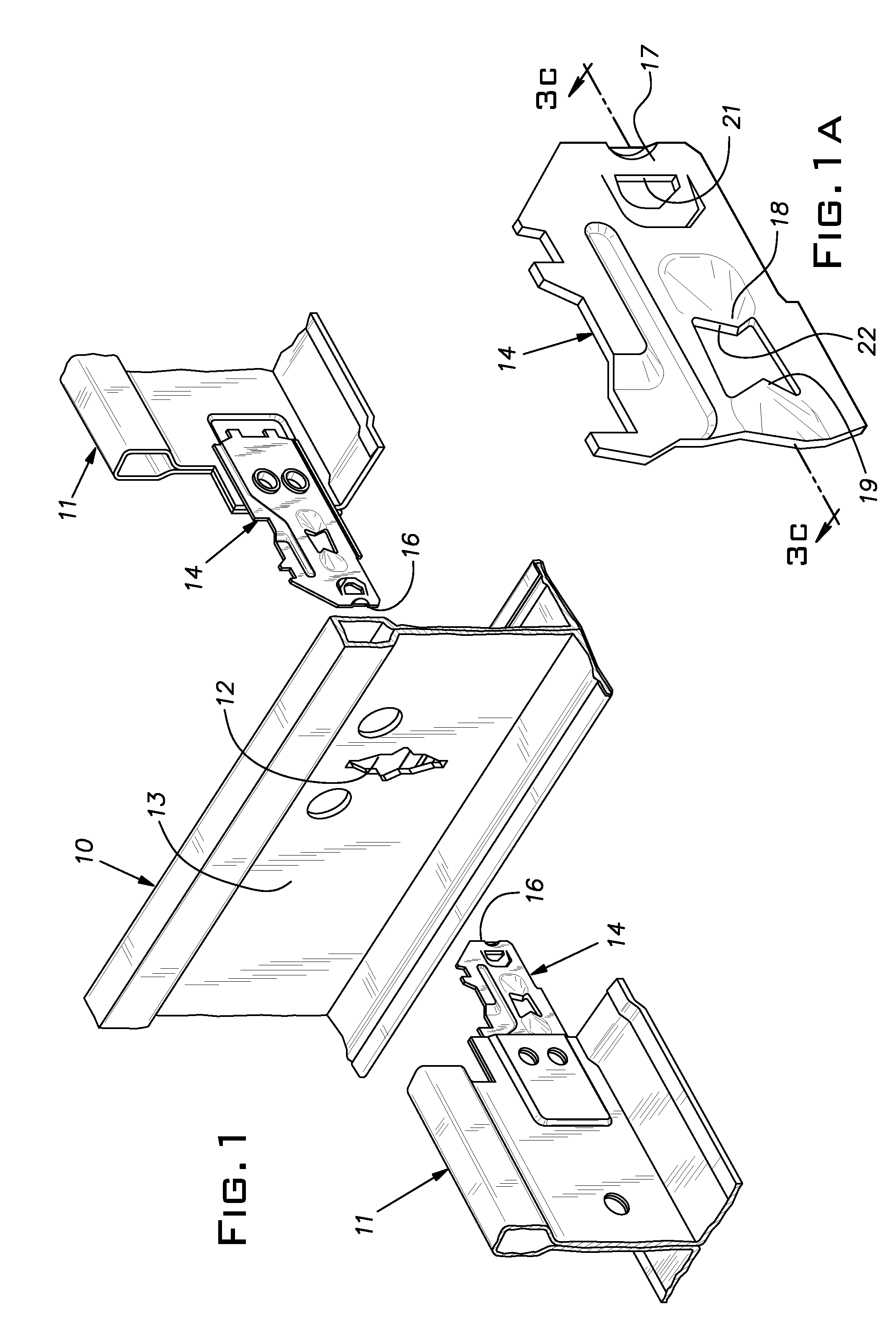
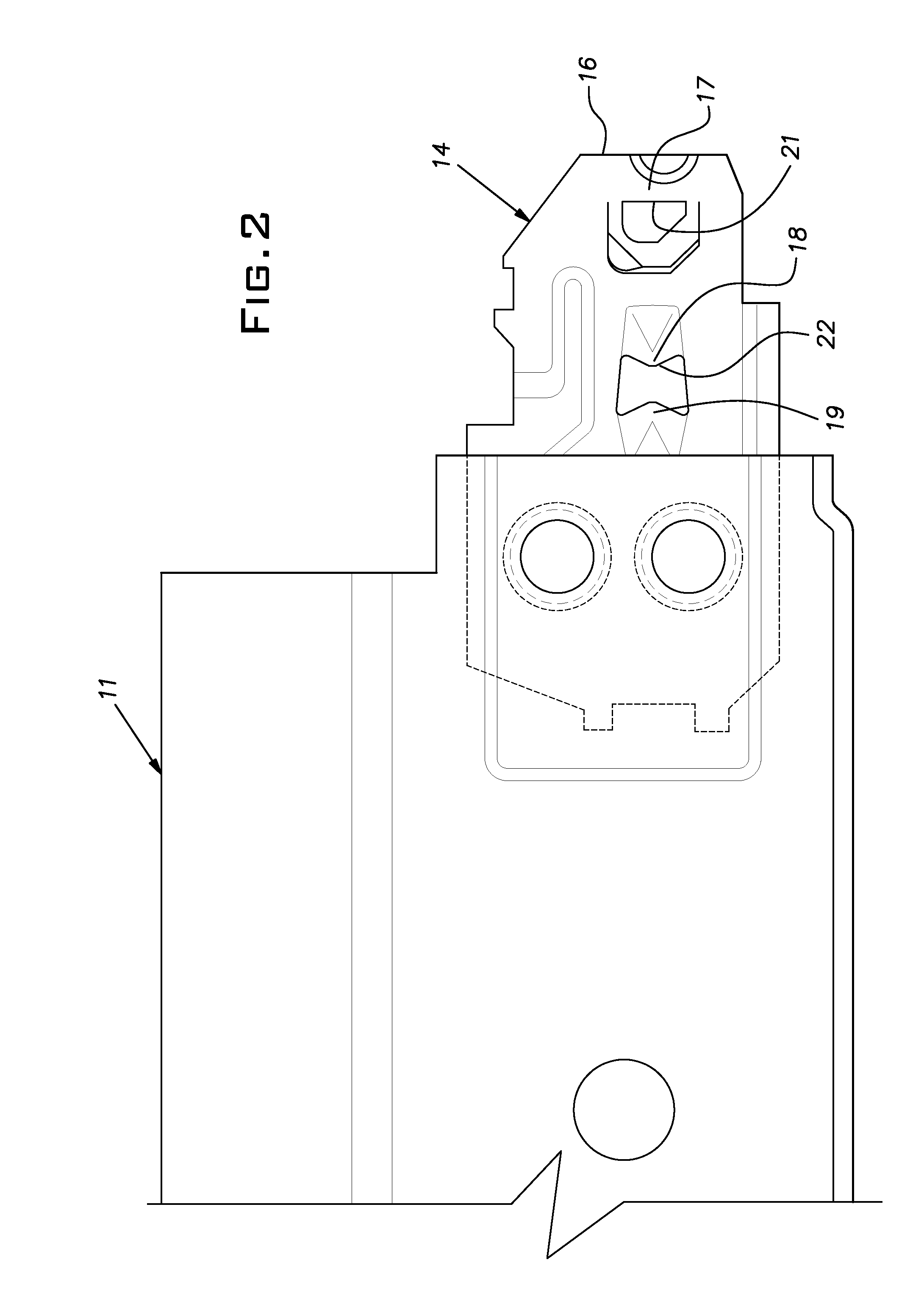
[0010]Referring now to the drawings and in particular to FIG. 1, portions of generally conventional suspended ceiling grid runners, in the form of tees 10, 11, are depicted. A main tee 10 has a vertically oriented slot 12, one of many at regularly spaced intervals along its length in a central web 13. End portions of opposed cross tees 11 are positioned in line with the main tee slot. The tees 10, 11 are preferably roll-formed from light gauge sheet metal stock as is customary. The main tee 10 can have a typical length of 10 or 12 feet or metric equivalent and the cross tees 11 can have lengths of 4 feet, 2 feet, and 1 foot, or metric equivalent. The cross tees 11 have identical end connectors or clips 14 fixed to their ends such as by staking portions of the tee sheet metal stock through holes provided in the connectors.

[0011]The illustrated connectors 14 are of the general type disclosed in U.S. Pat. Nos. 5,517,796 and 5,761,868, the disclosures of which are incorporated herein by...


PUM

PropertyMeasurementUnit
Fractionaaaaaaaaaa
Fractionaaaaaaaaaa
Thicknessaaaaaaaaaa

Abstract

An end clip for joining runners of suspended ceilings by coupling with an identical clip, the clip being stamped from sheet metal stock with lead and trailing ends, a lateral projection and a projection receiving area behind the lead end, the clip being arranged such that when an identical clip oriented in the opposite direction of the clip and caused to laterally overlap the clip the projection of the clip is locked in the receiving area of the identical clip and, vice versa, at least one of the projection and projection receiving area having a rearward facing sheared edge forming an acute angle with the clip plane resulting from being sheared with tooling having a clearance between tooling substantially greater than 10% of the thickness of the sheet from which the clip is stamped.

Description

BACKGROUND OF THE INVENTION[0001]The invention relates to improvements in suspended ceiling grid construction and, in particular, to improvements in connector clips for ceiling grid members.PRIOR ART[0002]Suspended ceiling grid members or runners typically comprise relatively long main runners and shorter cross runners. Both types of grid runners have connectors to join their ends to the ends of like members to construct a ceiling expanse of greater size than the length of individual main or cross runners. These end connectors, as the industry has advanced, are typically separate clip elements permanently attached to the grid runners themselves. The end connectors or clips are metal stampings, ordinarily of steel, formed with features that enable them to couple with identical units when one connector is pushed endwise into a lap joint with an opposing end connector. Depending on the clip design, the clips may directly abut or may have runner web areas disposed between them. In gener...

Claims


Application Information

Patent Timeline
IPC IPC(8): E04B9/00B21D53/36
CPCE04B9/122
Inventor LEHANE, JR., JAMES J.
Owner USG INTERIORS LLC
Learn More