Eureka AIR delivers breakthrough ideas for toughest innovation challenges, trusted by R&D personnel around the world.

Burner with flame ring stabilization chamber

a technology of flame ring and stabilization chamber, which is applied in the direction of gaseous heating fuel, combustion types, domestic stoves or ranges, etc., can solve the problems of not teaching not disclosing a chamber to stabilize the flame, and achieve the effect of maintaining flame stabilization

Inactive Publication Date: 2011-06-02
DESIGNGASPARTS
View PDF15 Cites 17 Cited by
  • Summary
  • Abstract
  • Description
  • Claims
  • Application Information

AI Technical Summary

Benefits of technology

[0024]In accordance with yet another aspect of the present invention, the burner flame ring is provided. The burner flame ring includes means for contacting a corresponding burner cap and means for retaining a gas / air mixture therein to preserve flame stabilization when pressure disturbances occur within the cooking appliance.

Problems solved by technology

Prior such devices were fabricated using welds, which fail over prolonged use.
The '631 patent does not teach a chamber to stabilize the flame
The '605 patent does not disclose a chamber to stabilize the flame.

Method used


Image

  • Burner with flame ring stabilization chamber
  • Burner with flame ring stabilization chamber
  • Burner with flame ring stabilization chamber

Examples


Embodiment Construction

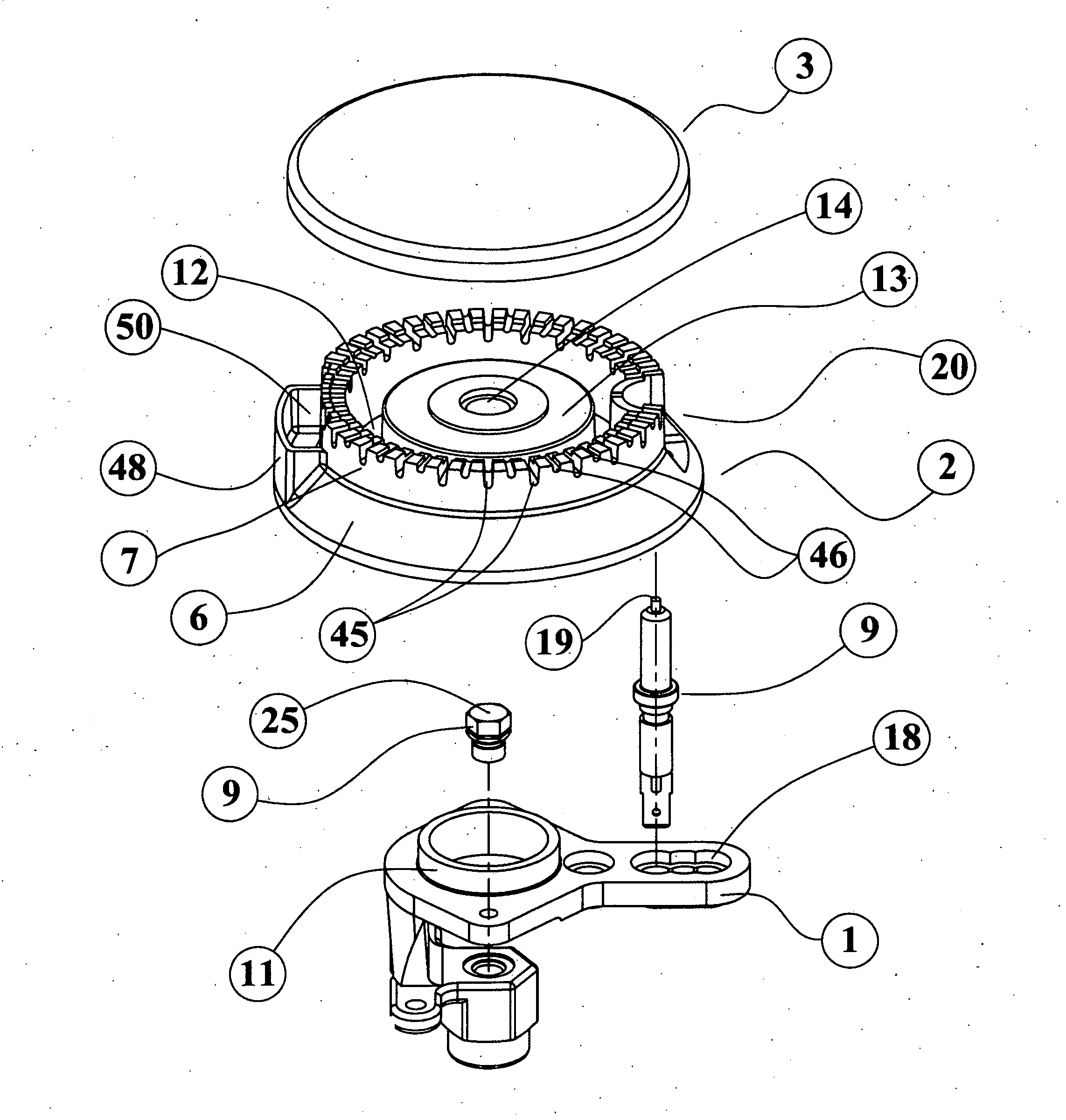
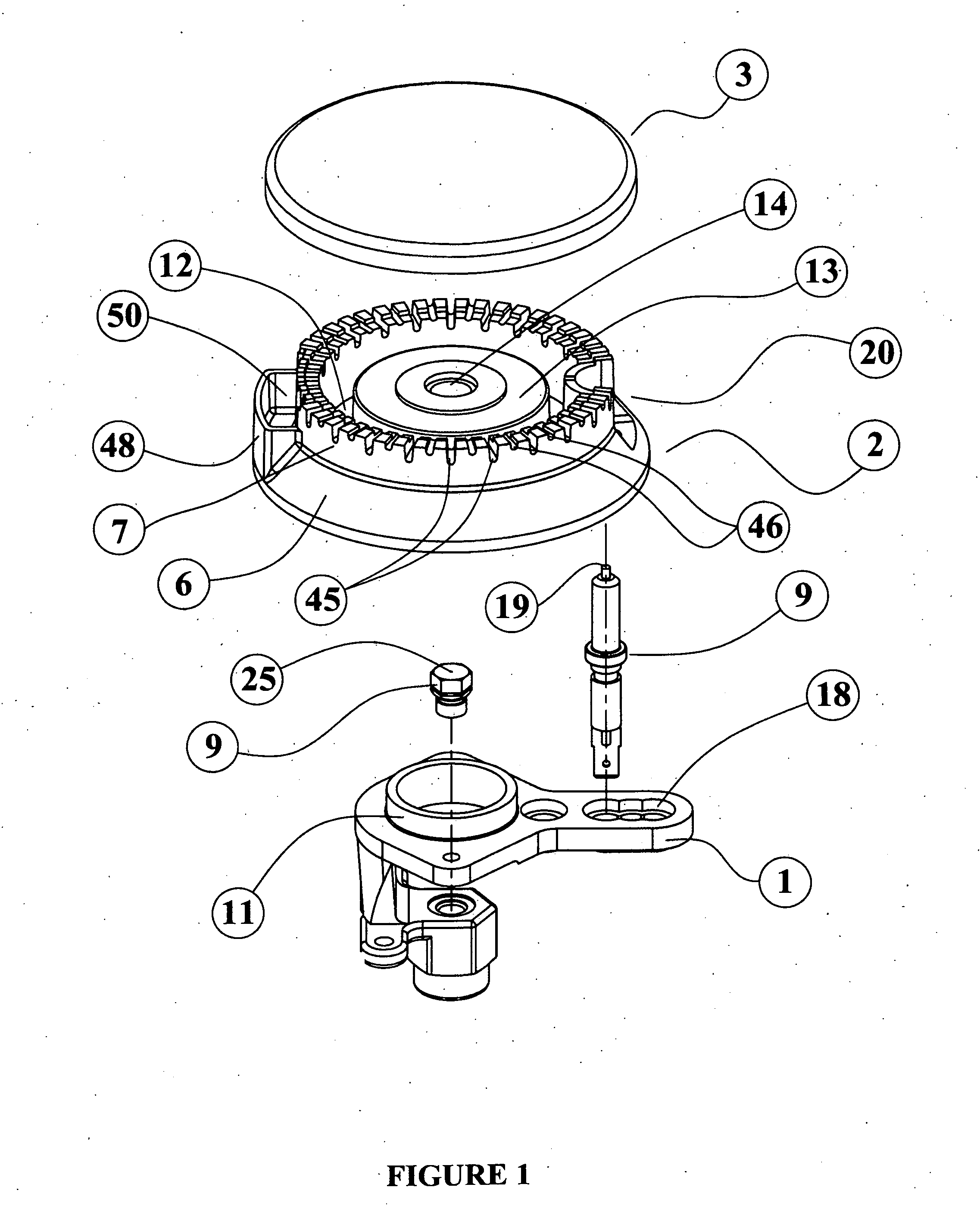
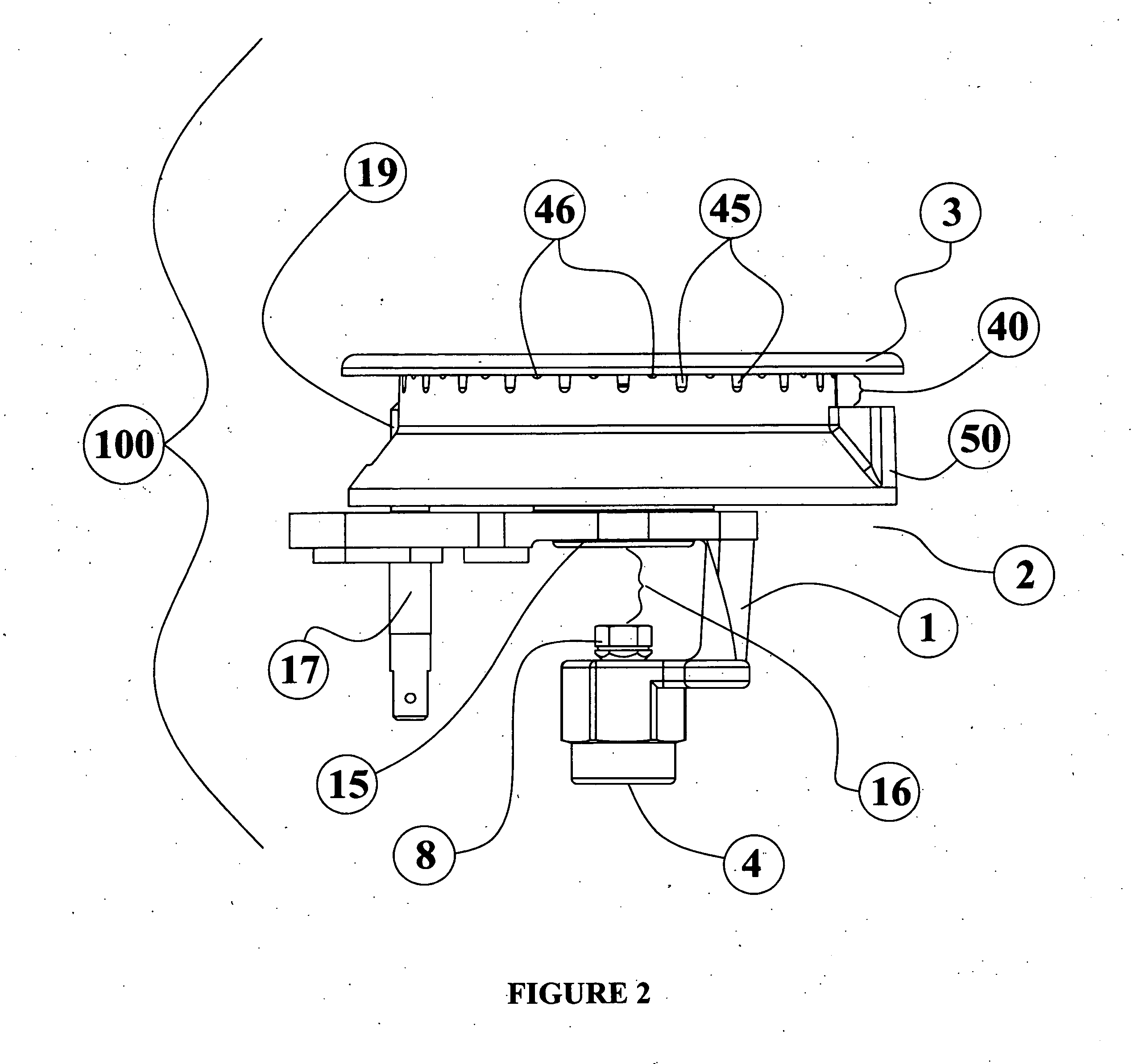
[0033]The present invention relates to a burner flame ring for a gas burner having at least one flame stabilization chamber provided therein. The flame stabilization chamber serves to retain a small amount of the gas / air mixture and preserve flame stabilization of the burner. The flame stabilization chamber is located on the outer wall of the burner flame ring. The small amount of the gas / air mixture that is caught inside the flame stabilization chamber is relatively isolated from the main burner chamber of the burner flame ring. When any gas / air flow or pressure changes occur in the ports of the burner flame ring, the gas / air mixture contained in the flame stabilization chamber is available to stabilize the flame at the ports and to preserve the correct performance of the burner.

[0034]The present invention is described with reference to the drawings and it is to be appreciated that the various drawings are not drawn to scale from one figure to another nor inside a given figure, and...


PUM


Abstract

Gas burners on modern kitchen cooking appliances are subject to fluctuations caused by drafts, breezes, etc. These burners will require flame stabilization chambers or another suitable engineering solution to overcome this problem. This invention describes a flame stabilization chamber that is constructed exterior to the main burner chamber and covered by the burner cap. The flame stabilization chamber acts to prevent extinguishing of the flame due to a random draft or breeze, by providing additional captured flammable gas / air so as to maintain the flame.

Description

BACKGROUND OF THE INVENTION[0001]1. Field of the Invention[0002]The present invention relates to burner flame rings, and more particularly, to the burner flame rings used on gas cooking appliances as a part of atmospheric gas burners and having a flame stabilization chamber therein.[0003]2. Summary of the Invention[0004]Current household cooking appliances are equipped by atmospheric gas burners in different sizes. Regardless of their size, a significant factor in the performance of gas burners is their ability to withstand airflow disturbances in the surroundings, such as room drafts, rapid movement of cabinet doors, or rapid oven door manipulation, especially if the gas burner is working at its minimum gas flow input. Manipulation of the oven door is particularly troublesome because rapid openings and closings of the oven door cause fast changes of pressure conditions within the gas stove, such as under-pressure and over-pressure.[0005]A large amount of the air that passes through...

Claims


Application Information

Patent Timeline
Patent Type & Authority Applications(United States)
IPC IPC(8): F23Q25/00
CPCF23D14/06F24C3/126F24C3/103F23D2207/00
Inventor HARNEIT, UWE
Owner DESIGNGASPARTS
Why Eureka
Eureka Blog
Learn More