
Image Processing Apparatus, Image Processing Method, and Computer Program

a technology of image processing and image processing method, applied in the field of image processing apparatus, image processing method, and computer program, can solve problems such as difficulty in reducing processing time, achieve high speed, reduce processing time, and suppress the appearance of unnecessary multi-valued images

Inactive Publication Date: 2011-06-02
KEYENCE
View PDF0 Cites 2 Cited by
  • Summary
  • Abstract
  • Description
  • Claims
  • Application Information

AI Technical Summary

Benefits of technology

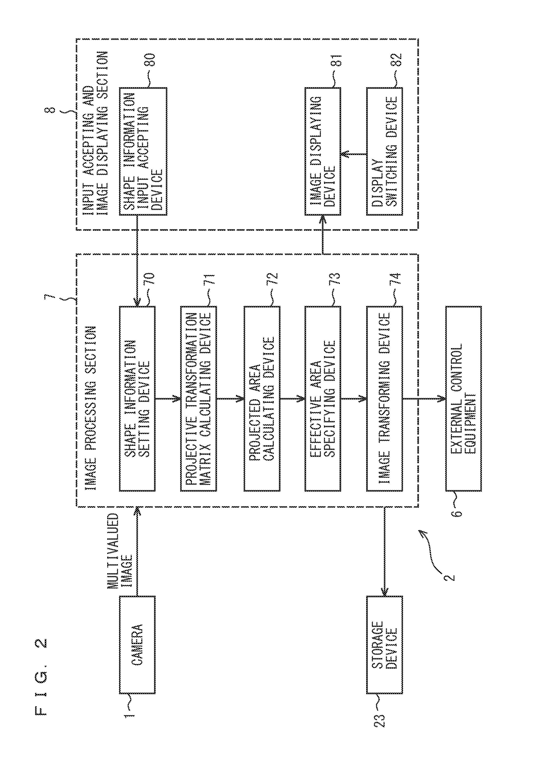
The present invention relates to an image processing apparatus and method that can reduce processing time and suppress the appearance of unnecessary virtual images when performing projective transformation on a multivalued image. The apparatus includes a projective transformation parameter calculating device, a projected area calculating device, an effective area specifying device, and an image transforming device. The apparatus can also include a shape information input accepting device for specifying shapes of the imaging object before image processing. The transformation target area setting device can set a predetermined area including specific pixels or pixels inside the shape of the imaging object as the transformation target area. The image processing method can execute image processing on the multivalued image based on the transformation target area and the projective transformation parameter calculated by the method.

Problems solved by technology

There has thus been a problem in that it is difficult to reduce processing time, so as to complete image processing at high speed.
Further, in the case of a multivalued image with a distant background appearing therein other than the imaging object and large perspective distortion of the multivalued image of the imaging object, there has also been a problem in that an unnecessary multivalued image (virtual image), whose polarity based upon a predetermined condition for projective transformation is a reverse polarity, might be included other than an image as an object to be transformed by projective transformation.

Method used


Image

  • Image Processing Apparatus, Image Processing Method, and Computer Program
  • Image Processing Apparatus, Image Processing Method, and Computer Program
  • Image Processing Apparatus, Image Processing Method, and Computer Program

Examples


first embodiment

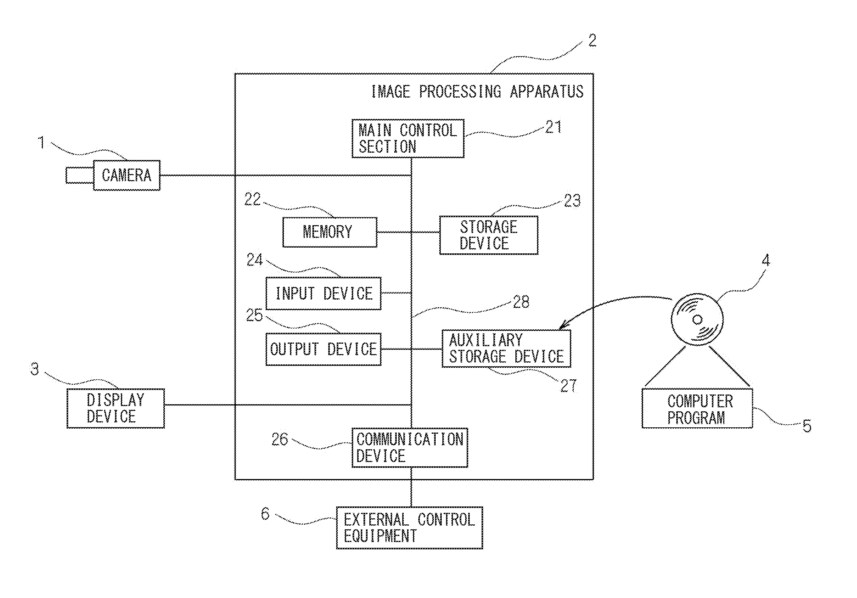
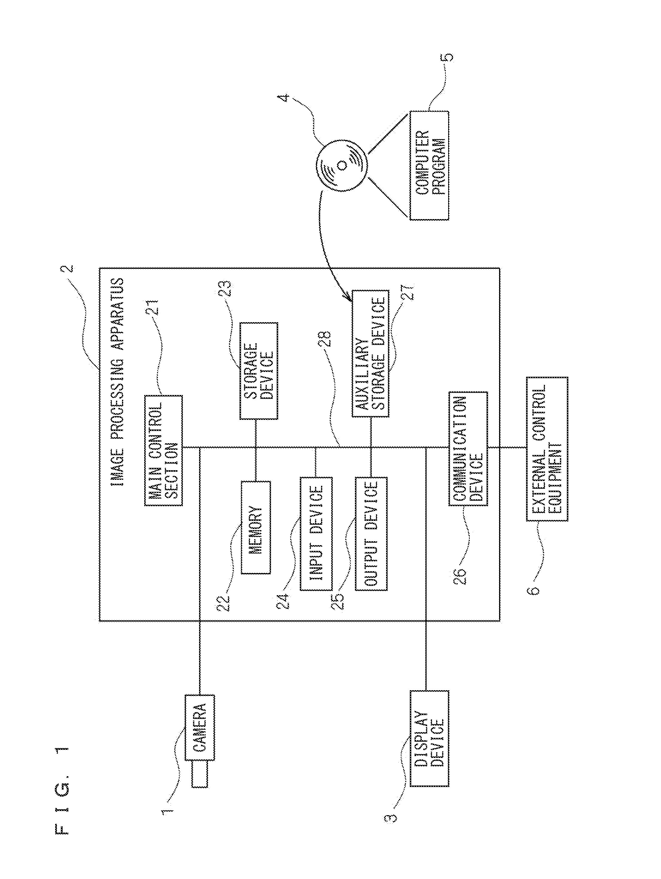
[0066]FIG. 1 is a block diagram schematically showing a configuration of an image processing apparatus according to the first embodiment of the present invention. As shown in FIG. 1, an image processing apparatus 2 according to the first embodiment is connected with a camera 1 as an imaging device for picking up a multivalued image, and a display device 3 for displaying a picked-up multivalued image or a projectively transformed multivalued image.

[0067]The image processing apparatus 2 is provided with a main control section 21 configured by at least a CPU (central processing unit), an LSI, or the like, a memory 22, a storage device 23, an input device 24, an output device 25, a communication device 26, an auxiliary storage device 27, and an internal bus 28 to which the above hardware components are connected. The main control section 21 is connected to the hardware components of the image processing apparatus 2 as described above via the internal bus 28, and controls operations of t...

second embodiment

[0100]FIGS. 9A and 9B are illustrative views of a multivalued image before image processing where large perspective distortion has occurred, and a multivalued image after image processing generated from the multivalued image before image processing by correcting the perspective distortion. FIG. 9A is a multivalued image before image processing where large perspective distortion has occurred and a distant background appears other than an imaging object 91. FIG. 9B is a multivalued image after image processing generated from the multivalued image before image processing shown in FIG. 9A by correcting the perspective distortion. As shown in FIG. 9B, a multivalued image 93 on the lower side of the figure is an unnecessary multivalued image (virtual image) whose polarity based upon a predetermined condition for projective transformation is a reverse polarity. In a second embodiment, there is described a configuration of the image processing apparatus 2 where performing projective transfo...


PUM


Abstract

In the case of executing image processing on a multivalued image obtained by picking up an image of an imaging object with a camera, the invention calculates a predetermined projective transformation parameter for projectively transforming a multivalued image before image processing, calculates a projected area obtained by projectively transforming an area where pixels of the multivalued image before image processing exist to an output area where pixels of a multivalued image after image processing exist based upon the calculated projective transformation parameter, specifies as an effective area an area in which the calculated projected area is overlapped with the output area where the pixels of the multivalued image after image processing exist, and performs coordinate transformation based upon the specified effective area and the calculated projective transformation parameter, to generate the multivalued image after image processing from the multivalued image before image processing.

Description

CROSS-REFERENCE TO RELATED APPLICATIONS[0001]The present application claims foreign priority based on Japanese Patent Application No. 2009-273983, filed Dec. 1, 2009, the contents of which is incorporated herein by reference.BACKGROUND OF THE INVENTION[0002]1. Field of the Invention[0003]The present invention relates to an image processing technology for projectively transforming a multivalued image picked up by an imaging device to correct perspective distortion of the multivalued image.[0004]2. Description of Related Art[0005]Conventionally, in apparatuses for picking up an image of a test object with an imaging device to inspect the test object and detect a defect thereof by use of the picked-up multivalued image, a variety of perspective distortion has occurred in accordance with a positional relation between the test object and the imaging device, a configuration of a lens, and the like. In many apparatuses, the picked-up multivalued image is appropriately projectively transfor...

Claims


Application Information

Patent Timeline
Patent Type & Authority Applications(United States)
IPC IPC(8): H04N5/228H04N23/40
CPCG06T3/00H04N5/2628H04N5/217H04N23/81
Inventor SHIMODAIRA, MASATO
Owner KEYENCE
Learn More