Blood pressure measurement device
a blood pressure measurement and blood pressure technology, applied in horology, instruments, angiography, etc., can solve the problems of reducing accuracy, adversely affecting the measurement, loss of inflating pressure, etc., and achieve the effect of improving the accuracy of blood pressure measurement results, small width, and reducing the accuracy of blood pressure measuremen
- Summary
- Abstract
- Description
- Claims
- Application Information
AI Technical Summary
Benefits of technology
Problems solved by technology
Method used
Image
Examples
first embodiment
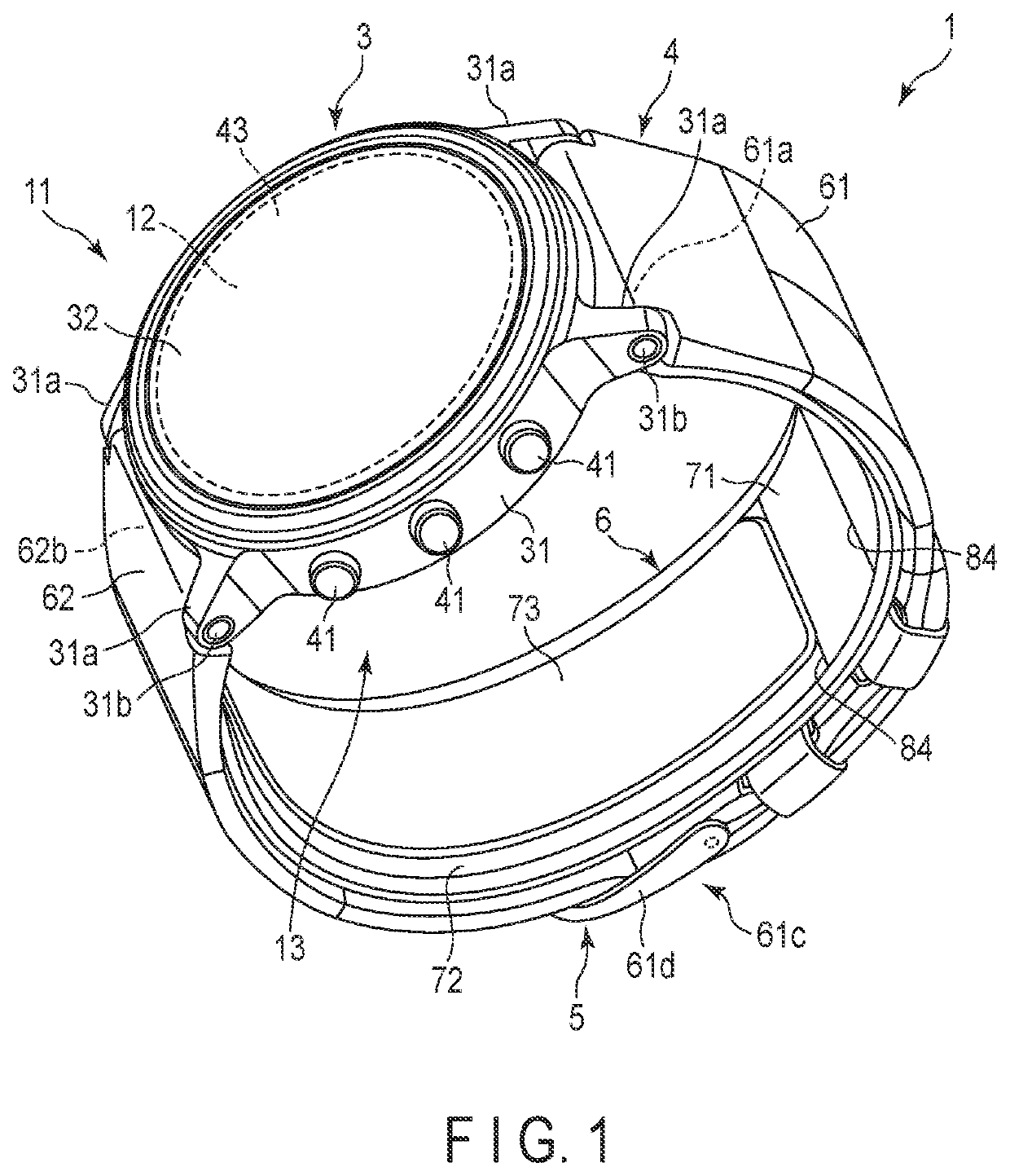
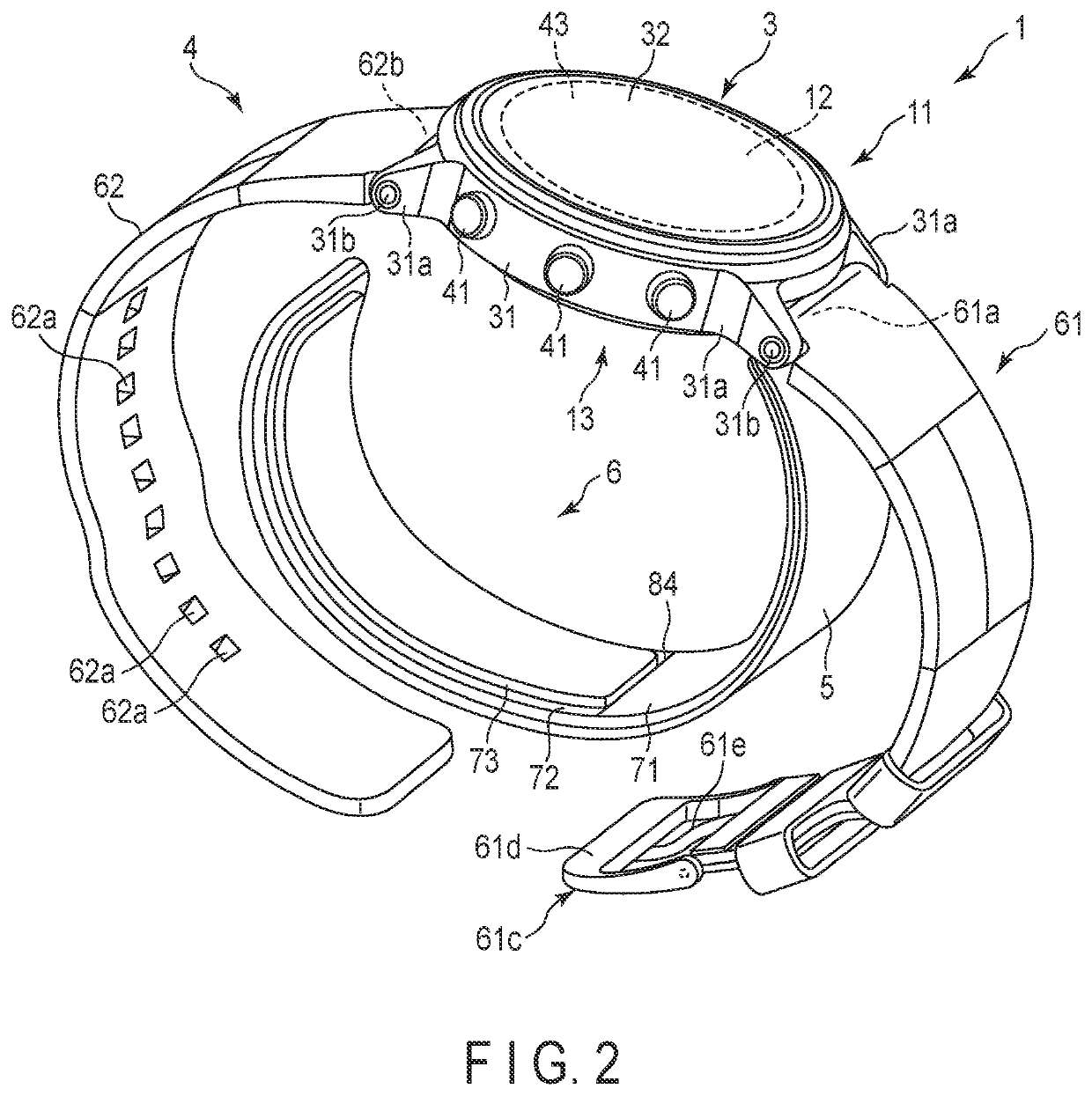
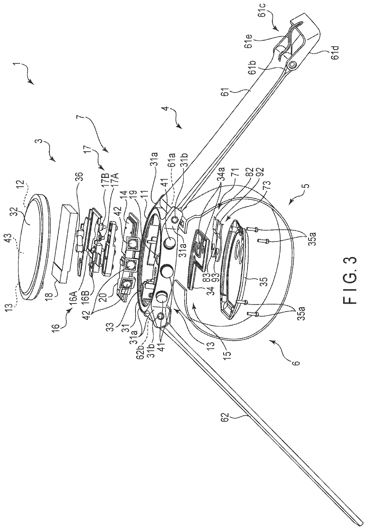
[0051]An example of a blood pressure measurement device 1 according to the first embodiment of the present invention will be described with reference to FIGS. 1 to 12.
[0052]FIG. 1 is a perspective view of the configuration of the blood pressure measurement device 1 according to the first embodiment of the present invention with a strap 4 buckled. FIG. 2 is a perspective view of the configuration of the blood pressure measurement device 1 with the strap 4 unbuckled. FIG. 3 is an exploded view of the configuration of the blood pressure measurement device 1. FIG. 4 is a block diagram of the configuration of the blood pressure measurement device 1. FIG. 5 is a perspective view of another configuration of the blood pressure measurement device 1. FIG. 6 is a perspective view of the configuration of the main body 3 of the blood pressure measurement device 1 viewed from the back cover 35 side. FIGS. 7 and 8 are plan views of the internal configuration of the main body 3 when viewed from the...
second embodiment
[0146]The pressing cuff 71A in the second embodiment will be explained with reference to FIGS. 18 and 19. The second embodiment differs from the blood pressure measurement device 1 according to the first embodiment in the pressing cuff adopted in the cuff structure 6, and therefore the structure other than the pressing cuff will be omitted from the explanation. In the present embodiment, the same numerals are used for the same structural components as those of the blood pressure measurement device 1 according to the first embodiment, and the detailed explanation thereof is omitted.
[0147]FIG. 18 is a plan view for schematically showing the structure of the pressing cuff 71A according to the second embodiment, and FIG. 19 is a side view for schematically showing the structure of the blood pressure measurement device 1 adopting the pressing cuff 71A, when inflated.
[0148]As illustrated in FIG. 18, a plurality of guides 84 are provided at regular intervals in the pressing cuff 71A. In su...
third embodiment
[0151]Next, the pressing cuff 71B according to the third embodiment will be explained with reference to FIGS. 20 and 21.
[0152]The third embodiment differs from the above-mentioned blood pressure measurement device 1 according to the first embodiment only in the structure of the pressing cuff adopted in the cuff structure 6, and therefore the structure other than the pressing cuff will be omitted from the explanation. Furthermore, in the present embodiment, the same numerals are used for the same structural components as those of the blood pressure measurement device 1 according to the first embodiment, and the detailed explanation thereof is omitted.
[0153]FIG. 20 is a plan view for schematically showing the structure of the pressing cuff 71B according to the third embodiment, and FIG. 21 is a side view for schematically showing the structure of the blood pressure measurement device 1 adopting the pressing cuff 71B, when inflated.
[0154]As illustrated in FIG. 20, a plurality of guides...
PUM
 Abstract
Description
Claims
Application Information
 - R&D
- Intellectual Property
- Life Sciences
- Materials
- Tech Scout
- Unparalleled Data Quality
- Higher Quality Content
- 60% Fewer Hallucinations
Browse by: Latest US Patents, China's latest patents, Technical Efficacy Thesaurus, Application Domain, Technology Topic, Popular Technical Reports.
© 2025 PatSnap. All rights reserved.Legal|Privacy policy|Modern Slavery Act Transparency Statement|Sitemap|About US| Contact US: help@patsnap.com


