
System for controling and calibrating single photon detection devices

a detection device and detection system technology, applied in the direction of optical radiation measurement, pulse technique, instruments, etc., can solve the problem that the sampling device and associated electronics may not operate at such high rates, and achieve optimal measurement, optimal measurement, and optimal measurement

Active Publication Date: 2011-06-02
NUCRYPT
View PDF14 Cites 61 Cited by
  • Summary
  • Abstract
  • Description
  • Claims
  • Application Information

AI Technical Summary

Benefits of technology

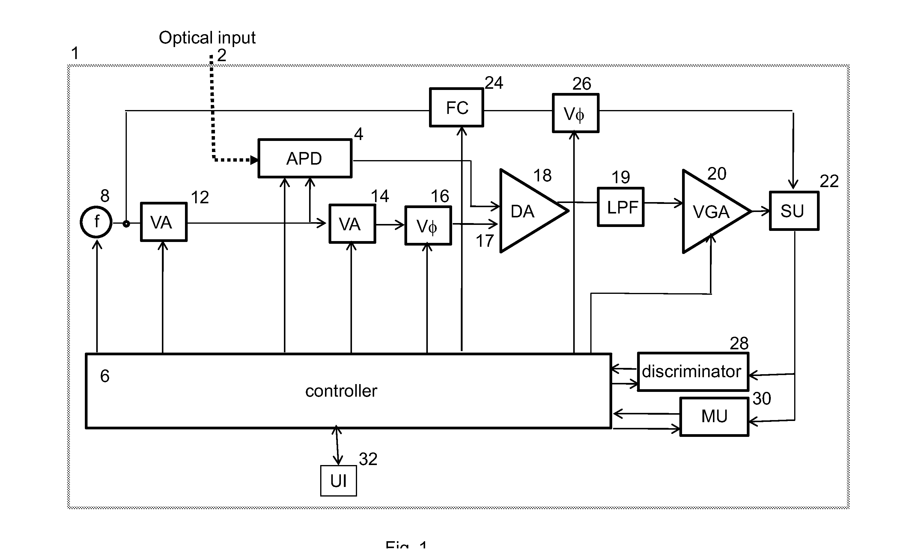
[0014]Especially when multiple SPDs are being monitored, as may happen for instance when performing a quantum state tomographic measurement, it is helpful to use T / H circuits to sample the output of the SPDs with the T / H output being sent both to a comparator in order to threshold the breakdown signal as well as to a multiplexer. The multiplexer can select one of the multiple input signals to be sent to its output and which of the multiplexer input signals is selected is controlled by the control unit. The multiplexer input singles each represent a sampled output of one of the SPDs. The desired signal to be monitored is selected by the control unit and the corresponding output of the multiplexer is sent out to an ADC to digitize the desired signal. The ADC sends the digitized signal into the monitor unit (MU). Note that the MU may be implemented in the same electrical platform as the control unit, such as in a field programmable gate array (FPGA) or integrated circuit. The T / H circuits may be operated at a sampling frequency significantly below the gate frequency during the monitoring period so that a low rate inexpensive ADC can be used as the front end digitizer for the monitor unit. By employing a multiplexer the number of ADCs required in the system can be reduced, simplifying the system.
[0017]It is possible for the DAC to lengthen the pulse width, including making it a continuous wave (CW) signal. Thus the gate duration can be lengthened for detecting temporally longer pulses. The system could even choose to pull the APD out of Geiger mode into linear mode if desired, for instance to increase the dynamic range of a particular measurement. The presence of the reference optical signal allows the resulting detection efficiency to be characterized easily, even if the APD performance changes over time.
[0019]One application for the use of multiple detectors is in quantum state tomography. It is desirable to minimize the measurement time in such a system, but optimal measurement time for a given accuracy will depend on the SPD characteristics and the characteristics of the input state being measured. An initial measurement of the optical input state can be made which the control unit can use to estimate the properties of the input optical signal. The control unit can use this information to update the SPD parameters so as to more optimally measure the input state, allowing for faster and / or more accurate tomographies.

Problems solved by technology

However, the sampler and associated electronics may not operate at such high rates, especially if multiple SPDs are being operated by one system and where it is undesirable to have many such complex and expensive high speed samplers.

Method used


Image

  • System for controling and calibrating single photon detection devices
  • System for controling and calibrating single photon detection devices
  • System for controling and calibrating single photon detection devices

Examples


Embodiment Construction

[0026]In the following description, for purposes of explanation, numerous specific details are set forth in order to provide a thorough understanding of the invention. It will be apparent, however, to one skilled in the art that the invention can be practiced without these specific details.

[0027]Reference in this specification to “one embodiment” or “an embodiment” means that a particular feature, structure, or characteristic described in connection with the embodiment is included in at least one embodiment of the invention. The appearances of the phrase “in one embodiment” in various places in the specification are not necessarily all referring to the same embodiment, nor are separate or alternative embodiments mutually exclusive of other embodiments. Moreover, various features are described which may be exhibited by some embodiments and not by others. Similarly, various requirements are described which may be requirements for some embodiments but not other embodiments. In general,...


PUM


Abstract

A single photon detection system and method are disclosed which have a control block for helping to monitor and optimize performance, especially at high detection rates. The system is based on photon detectors constructed with avalanche photodiodes (APD) gated in time to operate in the Geiger mode. An electrical reference frequency is generated which is subtracted from the APD output in order to better isolate the breakdown event. The resulting signal is sampled and analyzed to allow the control unit to optimize the magnitude and phase of the electrical reference frequency. The control unit may also change the gate pulse shape and phase, including by the use of a digital-to-analog converter. The gate pulse can be shifted off an input optical pulse so as to estimate dark count rate, or shifted to measure a reference input signal to estimate detection efficiency.

Description

CROSS-REFERENCE TO RELATED APPLICATIONS[0001]This application claims benefit of U.S. provisional application No. 61 / 265,844 “System for controlling and calibrating single photon counting devices” filed Dec. 2, 2009.STATEMENT REGARDING FEDERALLY SPONSORED RESEARCH OR DEVELOPMENT[0002]The United States Government has certain rights to this invention pursuant to contract No. W31P4Q-09-C-0115 from the Defense Advanced Research Projects Agency (DARPA) and contract No. FA9550-10-C-0079 from the Air Force Office of Scientific Research (AFOSR).FIELD OF THE INVENTION[0003]The present invention relates to measuring single photons using a photon detection system. In particular it pertains to controlling and calibrating the single photon detectors for reliable and monitored performance at high rates.BACKGROUND[0004]Single photon counting is useful for many applications, including the measurement of quantum states in tomography or in quantum key distribution systems, as well as in a wide variety...

Claims


Application Information

Patent Timeline
IPC IPC(8): G01D18/00G01J1/44H03K17/78
CPCG01J1/44H03K17/78G01D18/00
Inventor KANTER, GREGORY S.
Owner NUCRYPT
Learn More