
Sedimentation basin for sewage treatment plants

a sewage treatment plant and sedimentation basin technology, applied in the direction of sedimentation settling tanks, stationary filter elements, feed/discharge, etc., can solve the problems of space requirements and material costs involved in building such a sedimentation basin, water has a relatively long residence time, and the operation of the sewage treatment plant is interrupted, etc., to achieve the effect of reducing space requirements and high waste water throughput ra

Inactive Publication Date: 2011-06-02
SCHLEDERER SWANTJE MIGNON
View PDF14 Cites 4 Cited by
  • Summary
  • Abstract
  • Description
  • Claims
  • Application Information

AI Technical Summary

Benefits of technology

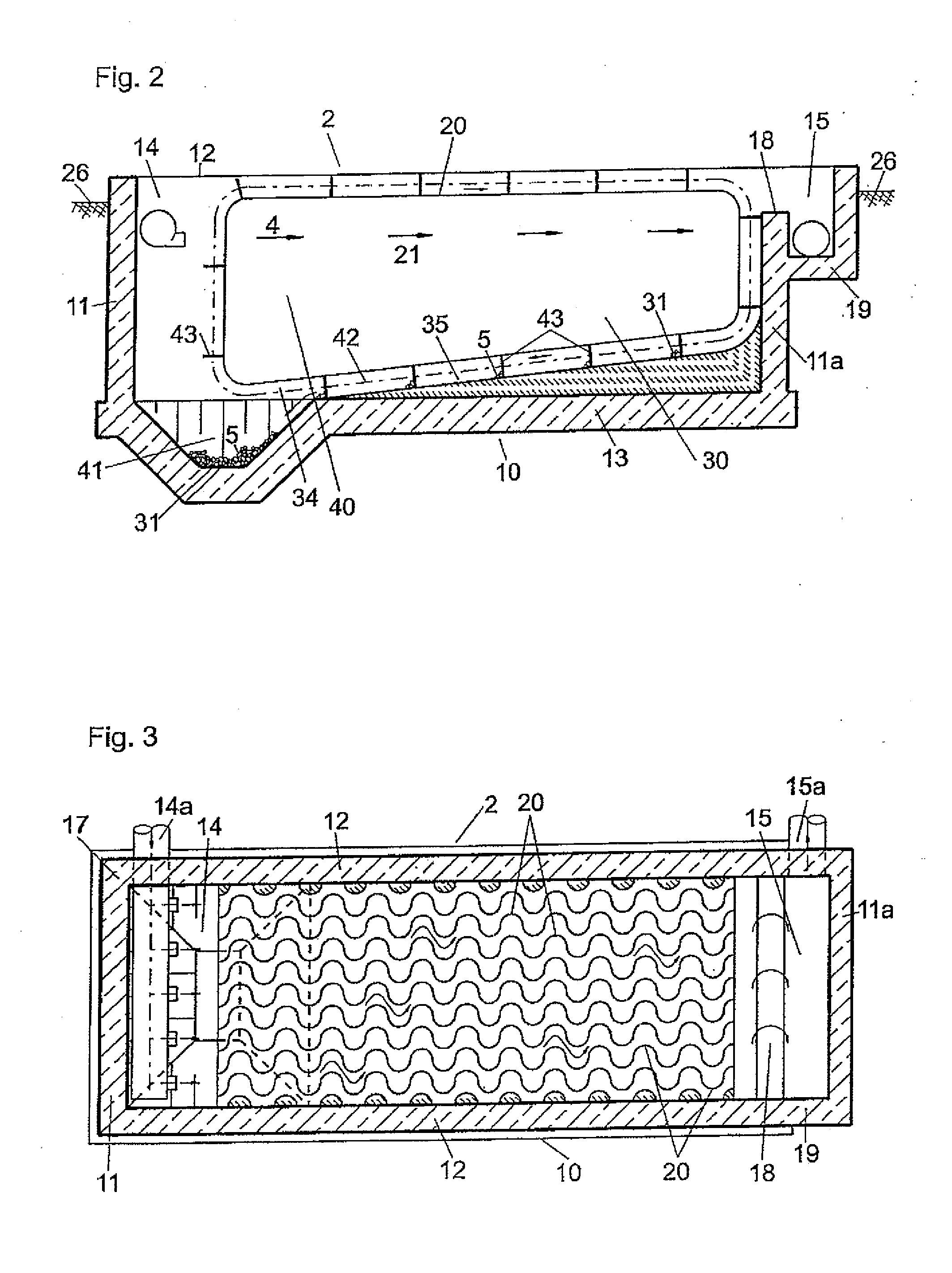
[0014]It is an object of the invention to provide a more efficient sedimentation basin for sand, rocks and other settleable matter entrained by waste water, which has a high waste water throughput rate and reduced space requirements.
[0015]The present invention uses an advantageously slow waste water flow for sedimenting entrained matter having higher specific weights, and employs structure that effects forced directional changes of the flow, resulting in alternating turbulent and stagnating zones, which promote the sedimentation process.
[0016]Such directional changes occur in natural bodies of flowing water that entrain bed loads, such as sand, gravel and rocks, in regions having low gradients and therefore low flow rates. Rivers of this sort are referred to as “meanders,” taking the name from a river in Asia Minor. In general, they develop in the lower course of the body of water. The cause of the meander shape is the effect of the inertia of the water, as a result of which the outside radius of the river bend, which is referred to as the cut bank, is subject to greater erosion than the inside radius of the river bend, which is known as the point bar. Once a bend has been formed, it therefore continues to become more pronounced. Once the channel line has been diverted from the center of the river to one of the banks, a cut bank forms, which continually recedes due to erosion of the side. Opposite the cut bank, the point bar is formed, from which the river moves away depositing sediments. As a result of the meandering course of the river, the flow rate is reduced, which generally promotes sedimentation.

Problems solved by technology

This matter can result in disruption (wear, clogging) of the operation of the sewage treatment plant, and must therefore be removed in advance from the flow of waste water that is to be purified.
Because of the depth, the waste water has a relatively long residence time, and thus the heavy sand can settle at the bottom of the tank.
However, this measure is only used to maintain the water level approximately constant over the length of the drain channel
The space requirements and material costs involved in building such a sedimentation basin can be problematic.

Method used


Image

  • Sedimentation basin for sewage treatment plants
  • Sedimentation basin for sewage treatment plants
  • Sedimentation basin for sewage treatment plants

Examples


Embodiment Construction

[0045]FIG. 1 shows a schematic illustration of a municipal sewage treatment plant 1, which is used to purify waste water 3 collected from drains and transported to the treatment plant. An inlet 14a leads to a collection tank 6 and then a grill 7, for sorting coarse, buoyant material, and then to a sedimentation basin 2. The purpose of the basin 210 is to remove coarse, settleable matter, such as sand, from the waste water. The raw waste water from which this matter has been separated enters an activated sludge basin 8, where organic and inorganic compounds are degraded by the action of microorganisms. In the secondary settling tank 9, suspended matter and other settleable impurities are precipitated as sewage sludge before the purified water flows via an outlet 15a into receiving water, typically a flowing body of water.

[0046]FIG. 2 shows a schematic illustration of a side view of a sedimentation basin 2,10 for sand according to the invention, configured as a rectangular elongate co...


PUM

PropertyMeasurementUnit
Lengthaaaaaaaaaa
Sizeaaaaaaaaaa
Shapeaaaaaaaaaa

Abstract

The invention relates to a sedimentation basin for sewage treatment plants, the sedimentation basin separating materials such as sand, rocks or broken glass, from waste water, which materials settle by gravitational action. The waste water is introduced in the inlet region of the sewage treatment plant. The sedimentation basin is provided with flow guide walls having a wave or meander shape, a plurality thereof being disposed vertically adjacent to each other and parallel to the main flow direction of the sedimentation basin. The slowing of the flow caused by this arrangement results in improved sedimentation that occurs in an efficient and compact basin requiring less space.

Description

BACKGROUND OF THE INVENTION[0001]The invention relates to a sedimentation basin for a sewage treatment plant for the purification of waste water collected in drain systems and transported to a sewage treatment plant.[0002]Biological, chemical and mechanical (also referred to as physical) methods are used to remove undesirable constituents from waste waters. Accordingly, modern sewage treatment plants have three stages, with special emphasis being placed on a particular method in each purification stage.[0003]The raw waste water that is fed from the drains comprises a mixture of different admixtures of organic and non-organic matter, which can be either soluble or insoluble and are carried along by the water, which forms the primary constituent. Particularly after heavy rainfall, which produces large amounts of sewage water, the waste water entrains considerable amounts of coarser, settleable impurities, such as sand, rocks and broken glass, and a variety of organic substances. This ...

Claims


Application Information

Patent Timeline
IPC IPC(8): B01D21/00B01D21/24
CPCB01D21/0045B01D21/0063B01D21/245B01D21/04B01D21/2427B01D21/0069
Inventor SCHLEDERER, SWANTJE MIGNON
Owner SCHLEDERER SWANTJE MIGNON
Learn More