
Systems and methods for controlling fuel mixing

a fuel mixing and system technology, applied in the direction of combustion control, machines/engines, lighting and heating apparatus, etc., can solve the problems of increasing the cost of fuel, and reducing the service life of the combined gas

Inactive Publication Date: 2011-06-02
GENERAL ELECTRIC CO
View PDF13 Cites 33 Cited by
  • Summary
  • Abstract
  • Description
  • Claims
  • Application Information

AI Technical Summary

Problems solved by technology

However, the conventional systems often mix the gases in a set ratio or provide relatively limited functionality for adjusting the mixture of the gases.
Accordingly, during changes in the operating condition of the gas turbine, such as transient events and / or load changes, the combined gas may not satisfy the power requirements of the gas turbine even if a flow of the combined gas is increased.
Additionally, a set ratio may utilize a greater quantity of a high heating value gas than is necessary for suitable operation of the turbine, thereby leading to higher fuel cost.

Method used


Image

  • Systems and methods for controlling fuel mixing
  • Systems and methods for controlling fuel mixing
  • Systems and methods for controlling fuel mixing

Examples


Embodiment Construction

[0011]Illustrative embodiments of the invention now will be described more fully hereinafter with reference to the accompanying drawings, in which some, but not all embodiments of the invention are shown. Indeed, the invention may be embodied in many different forms and should not be construed as limited to the embodiments set forth herein; rather, these embodiments are provided so that this disclosure will satisfy applicable legal requirements. Like numbers refer to like elements throughout.

[0012]For purposes of this disclosure, the term “machine” may refer to any suitable device, system, method, and / or combination of devices and / or systems and / or methods that utilize fuel to operate. In certain embodiments, a machine may utilize multiple sources and / or types of fuel. Examples of machines include, but are not limited to, gas turbines, power generating devices, rotating machines, reciprocating engines, steam boilers, etc.

[0013]Disclosed are systems and methods for controlling the mi...


PUM


Abstract

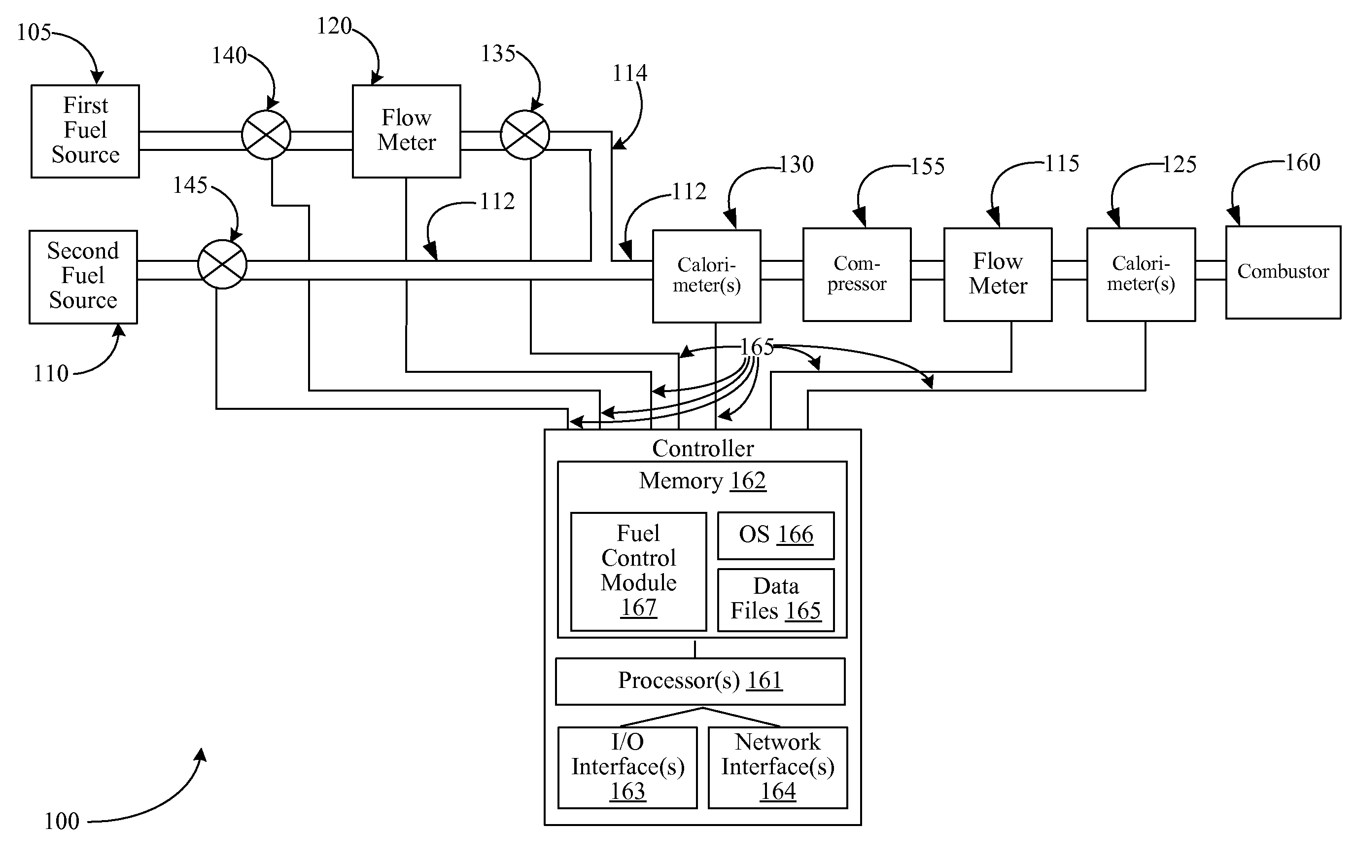
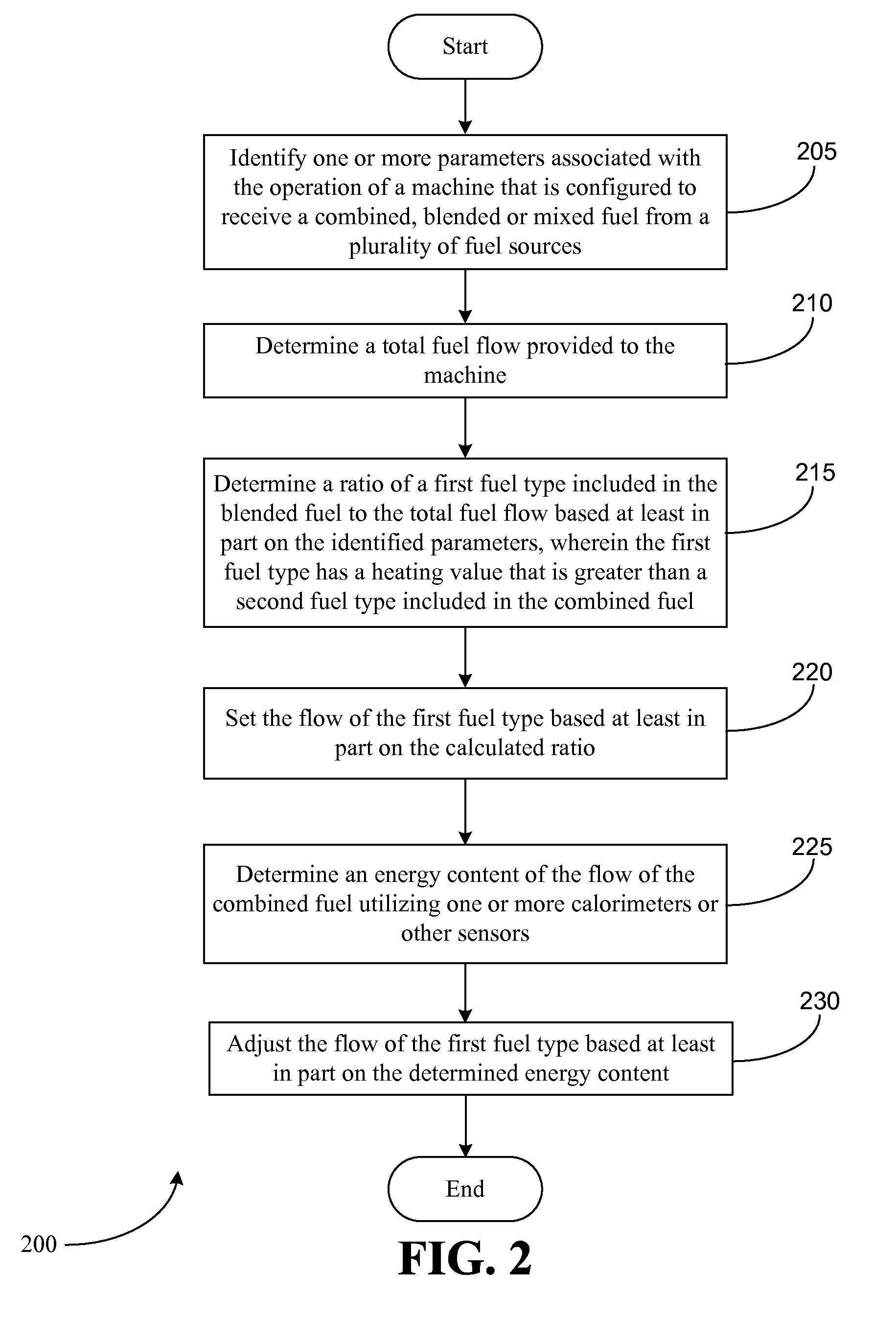
Systems and methods for controlling fuel mixing are provided. One or more parameters associated with the operation of a machine configured to receive a combined fuel may be identified. A fuel flow of the combined fuel that is provided to the machine may be determined. Based at least in part on the identified parameters, a ratio of a first fuel type included in the combined fuel to the determined fuel flow may be determined. The first fuel type may have a heating value that is greater than a second fuel type included in the combined fuel. A flow of the first fuel type may be set based at least in part on the ratio. Subsequent to setting the flow of the first fuel type, an energy content of the fuel flow of the combined fuel may be determined, and the flow of the first fuel type may be adjusted based at least in part on the determined energy content.

Description

FIELD OF THE INVENTION[0001]Embodiments of the invention relate generally to fuel-powered machines, and more specifically to systems and methods for controlling the mixing of fuel that is provided to a machine.BACKGROUND OF THE INVENTION[0002]Certain machines, such as gas turbines, power generating devices, etc., utilize fuel to power their operations. For example, a gas turbine may combust a fuel, such as natural gas, in order to rotate a turbine section and produce work. In certain industrial environments, one or more byproducts or discharges of other processes and / or systems may be utilized as fuel sources to power a turbine or other machine. These various fuel sources may be blended or mixed before they are provided to the machine. For example, in an iron mill, coke oven gas and blast furnace gas may be mixed in order to form a combined fuel source that is utilized to power a gas turbine.[0003]In conventional systems, a first fuel with a relatively high heating value is typicall...

Claims


Application Information

Patent Timeline
Patent Type & Authority Applications(United States)
IPC IPC(8): F02C9/40
CPCF02C7/22F02C9/40F02C9/44F23K2900/05004F23R2900/00002F23N2021/10F23N2037/08F23R3/36F23N1/002F23N2221/10F23N2237/08
Inventor LOEVEN, II, ROBERT J.
Owner GENERAL ELECTRIC CO
Learn More