Computer readable storage medium including effective light source calculation program, and exposure method
a computer-readable storage medium and light source technology, applied in photomechanical treatment, printing, instruments, etc., can solve the problems of enormous time and labor required in methods and the determination of effective light sources, and achieve the effect of reducing the decrease in image formation performan
- Summary
- Abstract
- Description
- Claims
- Application Information
AI Technical Summary
Benefits of technology
Problems solved by technology
Method used
Image
Examples
first embodiment
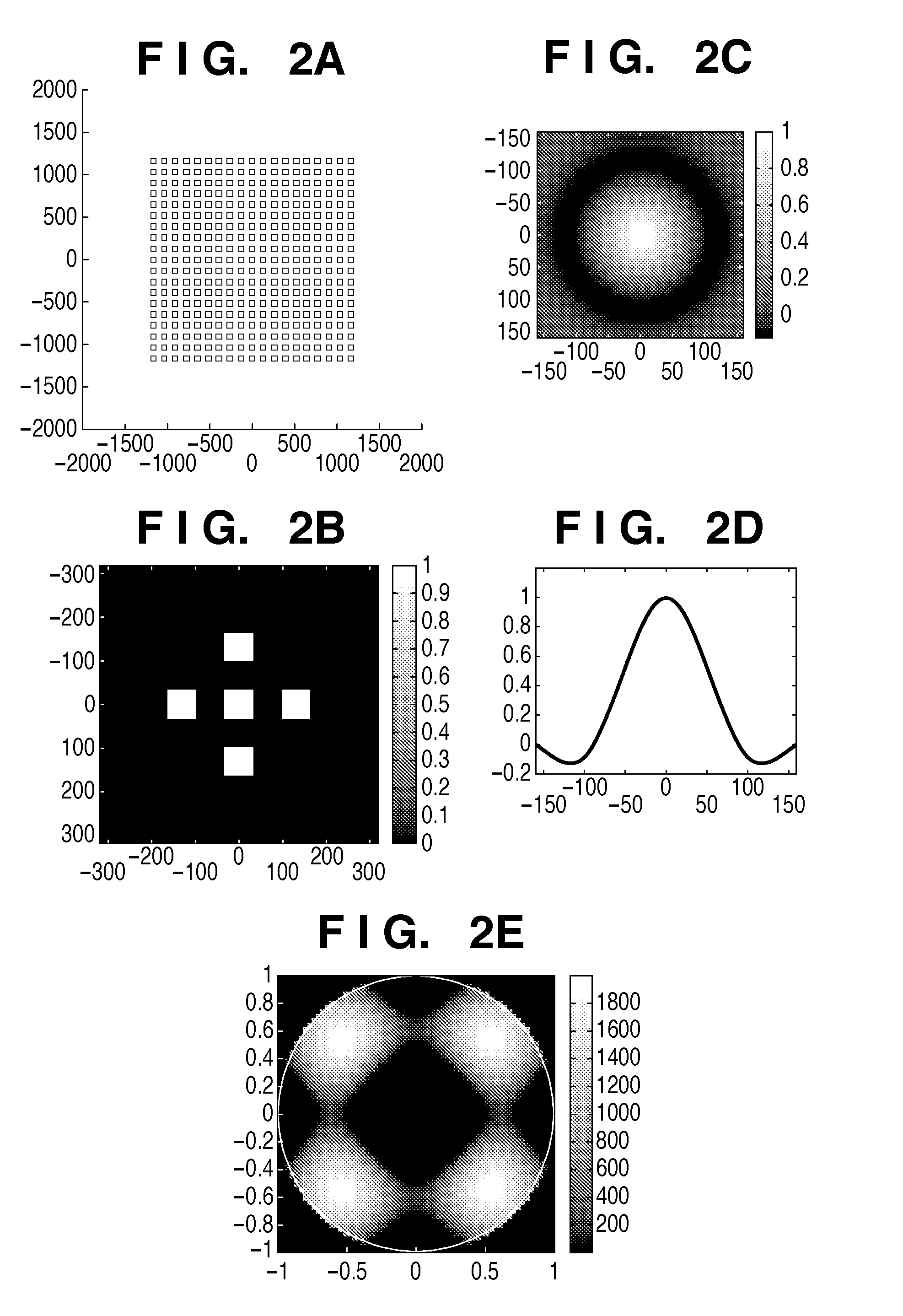
[0045]The first embodiment of a method of determining an effective light source will be explained below with reference to FIGS. 3A to 3F. FIG. 3A shows a target pattern to be formed on a substrate. Assume that the minimum half pitch HP of the target pattern is 65 (nm). When normalized by exposure light wavelength λ=193 (nm) and NA=1.35, the target pattern half pitch is k1=0.45. A mask was assumed to be a halftone phase-shift mask, the transmittance of the pattern was 100%, and that of the periphery of the pattern was 6%. A phase difference between the pattern and the periphery of the pattern is π (rad). In the target pattern, dense holes and isolated holes are arranged in the lateral direction. The target pattern is not a simple periodic pattern but includes the isolated holes, and this makes it difficult to balance the sizes of the isolated holes and dense holes. The ordinate and abscissa of FIG. 3A showing the pattern are indicated by a length (nm) converted into the length on the...
second embodiment
[0052]A method of determining an effective light source by using the same pattern example as in the first embodiment will be explained below. FIG. 5A shows a target pattern to be formed on a substrate. The minimum half pitch of the target pattern is HP=50 (nm). That is, since exposure light wavelength λ=193 (nm) and NA=1.35, the half pitch of the target pattern is k1=0.35. A mask was assumed to be a binary mask, the transmittance of the pattern was 1, and that of the periphery of the pattern was zero. FIGS. 5E and 5F illustrate an image function and effective light source derived by the second image function calculation method shown in FIG. 1B. FIG. 5E shows the image function, and FIG. 5F shows the effective light source.
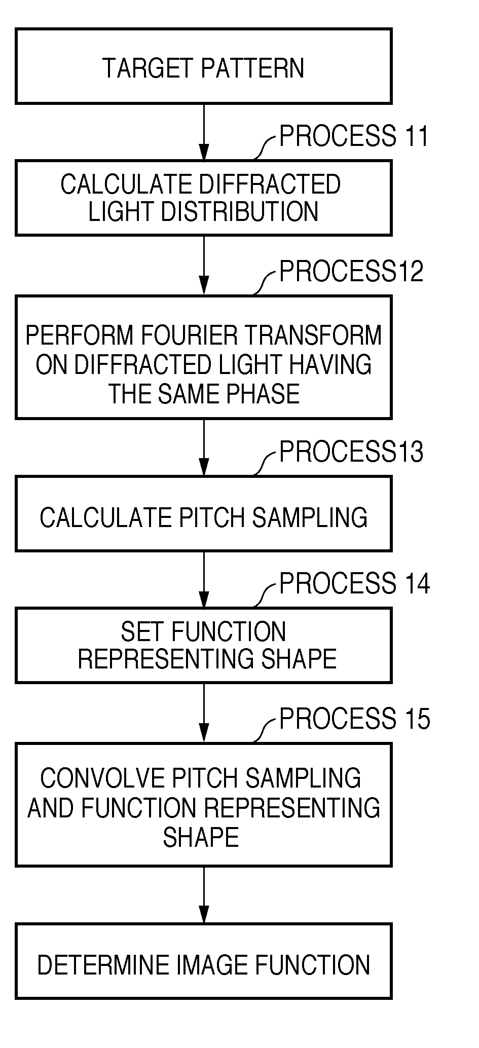
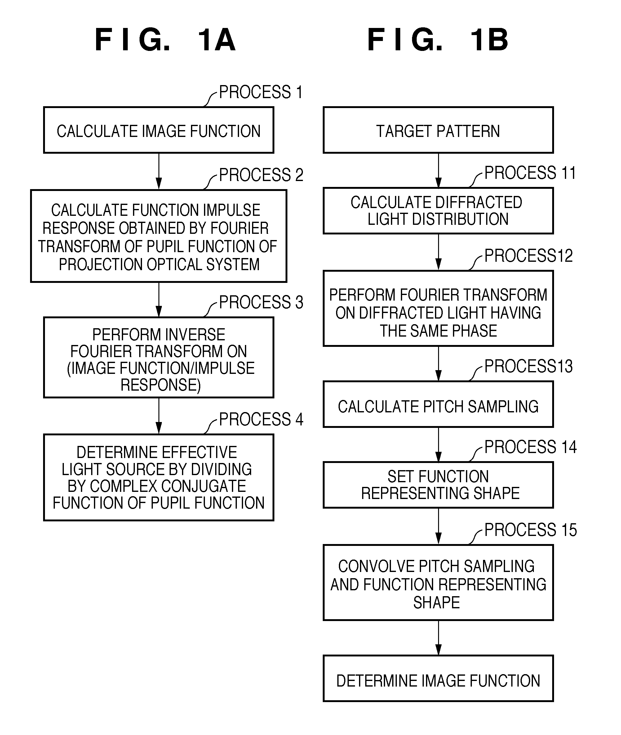
[0053]The image function deriving method using the second calculation method will be explained in detail below. To obtain pitch sampling from the target pattern, a computer obtained the diffracted light distribution of the target pattern. FIG. 5B shows the diffract...
third embodiment
[0057]A method of determining an effective light source by using an example of a brick wall pattern will be explained below. FIG. 7A shows a target pattern to be formed on a substrate. The half pitch of the target pattern in the lateral direction is HP=60 (nm). The half pitch of the target pattern in the lateral direction is HP=60 (nm). The pattern has a width of 60 (nm) and a length of 240 (nm). That is, since exposure light wavelength λ=193 (nm) and NA=1.35, the minimum half pitch of the target pattern is k1=0.42. A mask was assumed to be a binary mask, the transmittance of the pattern was 1, and that of the periphery of the pattern was zero.
[0058]In process 1, an image function was obtained by the second calculation method shown in FIG. 1B. In process 14 of FIG. 1B, as the function representing the shape of an element forming the target pattern, a function when the element shape was assumed to be an elliptic shape and a function when the element shape was assumed to be a circular...
PUM
 Abstract
Description
Claims
Application Information
 - R&D
- Intellectual Property
- Life Sciences
- Materials
- Tech Scout
- Unparalleled Data Quality
- Higher Quality Content
- 60% Fewer Hallucinations
Browse by: Latest US Patents, China's latest patents, Technical Efficacy Thesaurus, Application Domain, Technology Topic, Popular Technical Reports.
© 2025 PatSnap. All rights reserved.Legal|Privacy policy|Modern Slavery Act Transparency Statement|Sitemap|About US| Contact US: help@patsnap.com


