Composite lid for containers

a technology for containers and lids, applied in the field of lids, can solve the problems of presenting a relatively complex and onerous construction, unable to solve the solutions of metallic lids or plastic lids, and unable to solve the solutions of plastic lids, so as to improve the impermeability to oxygen and be less costly

Inactive Publication Date: 2011-05-26
BRASILATA S A EMBALAGENS METALICAS
View PDF5 Cites 5 Cited by
  • Summary
  • Abstract
  • Description
  • Claims
  • Application Information

AI Technical Summary

Benefits of technology

[0011]As a function of the limitations and drawbacks of the prior art composite lids, when related to the containers of the type considered herein, it is an object of the present invention to provide a lid in sheet metal and in plastic material, presenting an improvement in the impermeability to oxygen (and other gases) and light barrier, in relation to the lids formed only in plastic material, through a simple construction which is less costly than that of the known composite lids incorporating or not a tamper evident seal.
[0013]It is also a further object of the invention to provide a lid as defined above and which allows safely stacking the containers closed by said lids.
[0017]The lid formed according to the present invention has practically its whole area, designed for closing the container opening, defined by an opaque sheet metal plate being gas impermeable and with an extremely less production cost, allowing the retention portion in plastic material to operate as a sealing element, in cooperation with the seat, and as an element for axially retaining the lid to the tubular body of the container.

Problems solved by technology

However, the plastic-molded lids can present some limitations, in certain applications, regarding the gas and vapor impermeability, particularly during long shelf periods, and also the formation of an effective light barrier.
None of the solutions of metallic lid or plastic lid permit solving the problem of discarding the median scrap resulting from the stamping of the annular upper wall of the container.
These solutions present a relatively complex and onerous construction, not being applicable to lids to be fitted and retained on a seat defined on an annular upper wall of the container.

Method used


Image

  • Composite lid for containers
  • Composite lid for containers
  • Composite lid for containers

Examples


Embodiment Construction

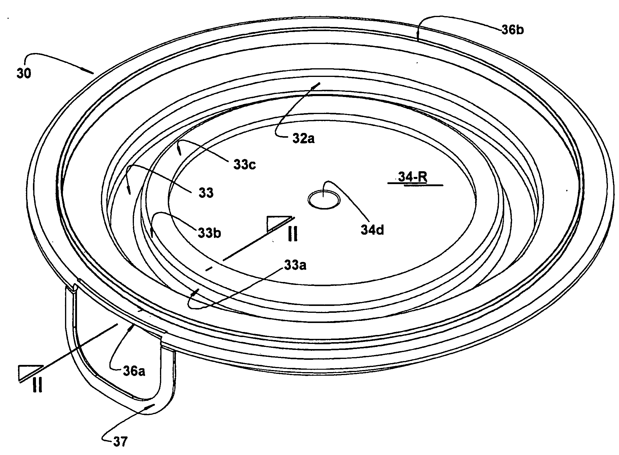
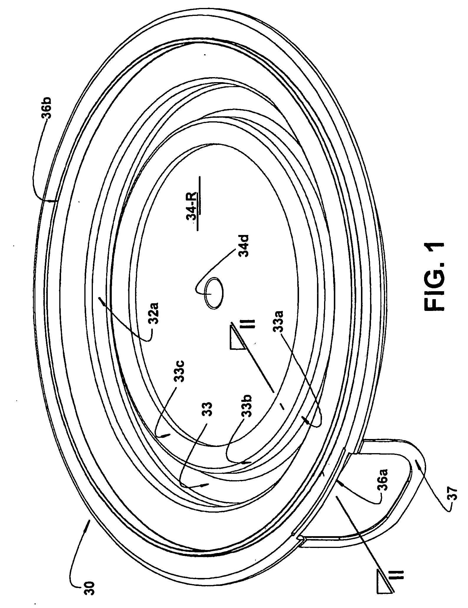
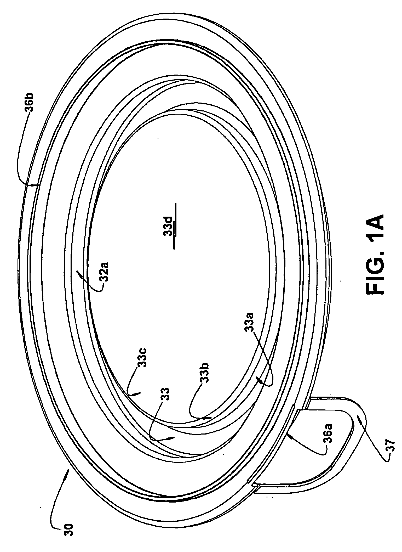
[0030]The composite lid of the present invention is applicable to containers of the type which comprises a tubular body 10 in sheet metal and having a usually cylindrical side wall 11, carrying an annular upper wall 20, also in sheet metal, presenting an opening A surrounded by a seat 21 against which is seated and retained a lid 30.

[0031]The annular upper wall 20 can be constructed in different ways as, for example, being formed by a deformed portion of the side wall 11 of the tubular body 10, as described in Brazilian Patent Application PI 0504528-2 (PCT / BR2005 / 000232) of the same applicant, or obtained in a separate sheet metal, being duly stamped and peripherally attached to an upper edge of the side wall 11 of the tubular body 10, as illustrated in FIGS. 2 and 8, by an upper double-seaming Rs.

[0032]Independently of the construction applied to the annular upper wall 20 (either a single piece or a piece double-seamed to the side wall 11 of the tubular body 10), it is constructed ...


PUM

PropertyMeasurementUnit
plasticaaaaaaaaaa
mechanical strengthaaaaaaaaaa
strengthaaaaaaaaaa

Abstract

A composite lid for a container that includes a tubular body carrying an annular upper wall made of sheet metal, in which is defined an opening surrounded by a seat, which is configured to receive and retain the lid. The lid includes a base portion peripherally incorporating a retention portion to be seated and retained on the seat when the lid is closed. The base portion includes a peripheral annular element molded in a plastic material as a single piece with the retention portion, and a central element in the form of a sheet metal plate that has an outer peripheral edge attached to the peripheral annular element. The peripheral annular element includes, internally and in a single piece, a central panel disposed on the central element, which is incorporated to the lid during its injection or attached thereto afterwards.

Description

FIELD OF THE INVENTION[0001]The present invention refers to a lid formed of multiple materials, more particularly in sheet metal and in plastic material, to be applied to a container generally defined by a can with a circular or polygonal cross-section, obtained in sheet metal or in other materials, comprising a tubular body carrying an annular upper wall, which defines an access opening to the interior of the container and a seat on which the lid is removably fitted and retained, for closing the container.PRIOR ART[0002]There are well known from the prior art the lids of cans or other similar containers, said lids being constructed in a single piece in stamped sheet metal or molded plastic material and presenting a base portion, which covers the opening of the container and peripherally incorporates a retention portion to be seated and retained on the seat, when the lid is closed.[0003]The lids formed in stamped sheet metal are generally deprived of a tamper evident seal portion, w...

Claims


Application Information

Patent Timeline
Patent Type & Authority Applications(United States)
IPC IPC(8): B65D43/02
CPCB65D43/021B65D2543/00083B65D2543/0024B65D2543/0087B65D2543/00435B65D2543/00509B65D2543/0074B65D2543/00314
Inventor ALVARES, ANTONIO CARLOS TEIXEIRASENE, ANTONIO ROBERTO
Owner BRASILATA S A EMBALAGENS METALICAS
Why Eureka
Try Eureka