Tank for containing liquids
a technology for liquid tanks and tanks, applied in the direction of liquid transfer devices, machines/engines, packaging, etc., can solve the problems of unusable chemicals being stored in such an amount inevitably entail an undesired, unsuitable for heat storage and retrieval, and inability to store and retrieve the heat of the amount of molten salts needed, etc., to achieve the effect of reducing the amount of molten salts
- Summary
- Abstract
- Description
- Claims
- Application Information
AI Technical Summary
Benefits of technology
Problems solved by technology
Method used
Image

Examples
example 1
State of the Art
[0149]A CSP plant requires the installation of a heat storage system of 1000 MWh capacity to be stored in 8 hours.
[0150]To satisfy these heat storage capacity requirements, a heat storage system according to the state of the art consists of a hot and a cold tanks each containing a molten salts mixture of 39÷41% KNO3 and 59÷61% of NaNO3 having an average specific heat capacity of 1.50 kJ / kg·° K. and an average density of 1.87 kg / m3 at a temperature range between 290° C. and 390° C. The temperature of the cold tank equals to 290° C. and the temperature of the hot tank equals to 390° C.
[0151]Such a heat storage system requires 24,000 tons of the molten salts mixture freely transferable from one tank to the other, with a flow rate of 3,000 ton / hour.
[0152]The arrangement selected requires 2 pumps for which the manufacturers usually require a net positive suction head of 5.0-5.2 m of liquid column corresponding to a molten salts level above the pump impeller of 0.70 m whic...
example 2
[0156]For satisfying the same heat storage capacity requirements of the CSP plant described in Example 1 a heat storage system comprising two heat storage tanks according to the present invention was designed.
[0157]Each tank was equipped with the same number and type of pumps of the tanks used in the heat storage system of Example 1.
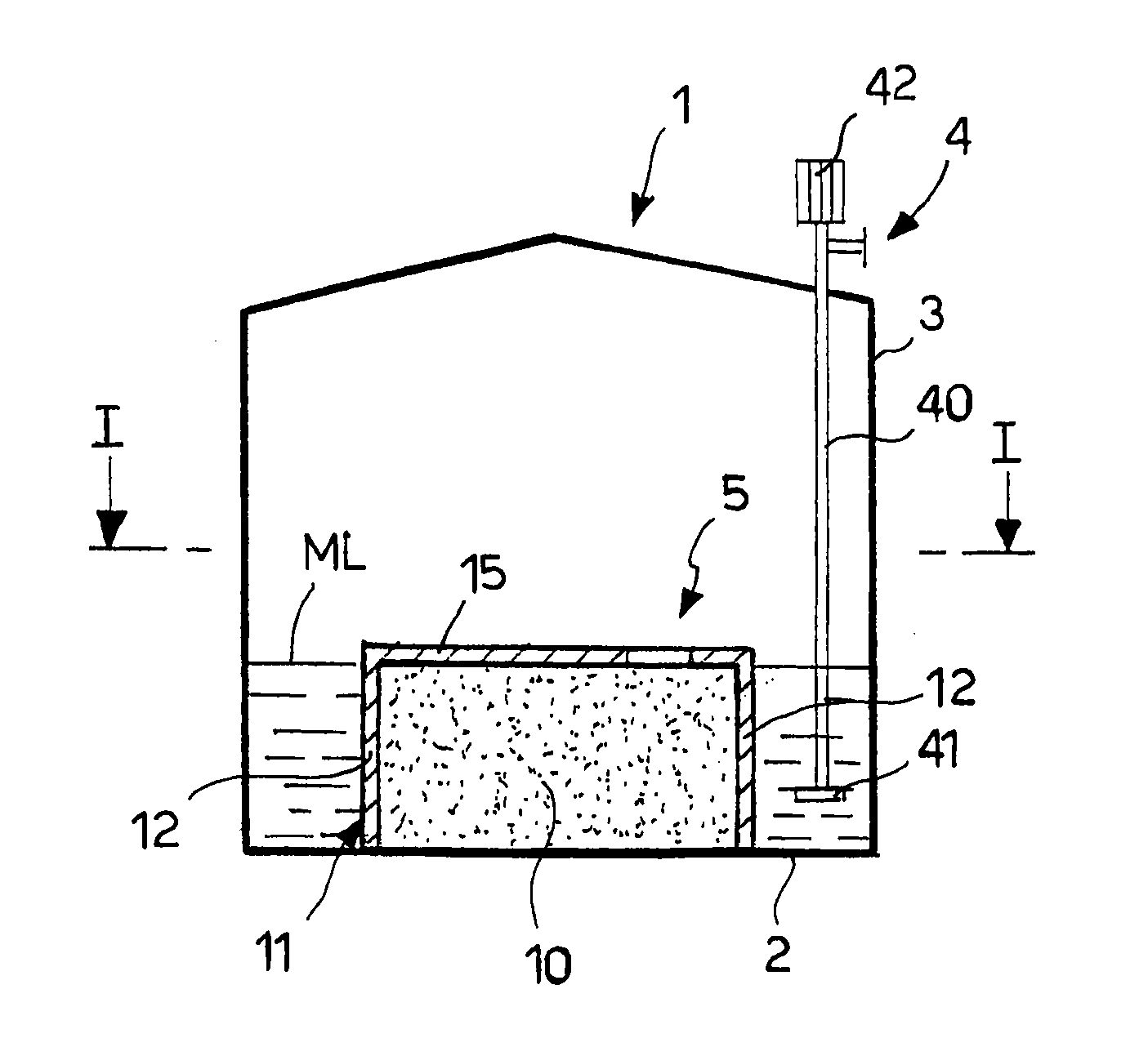
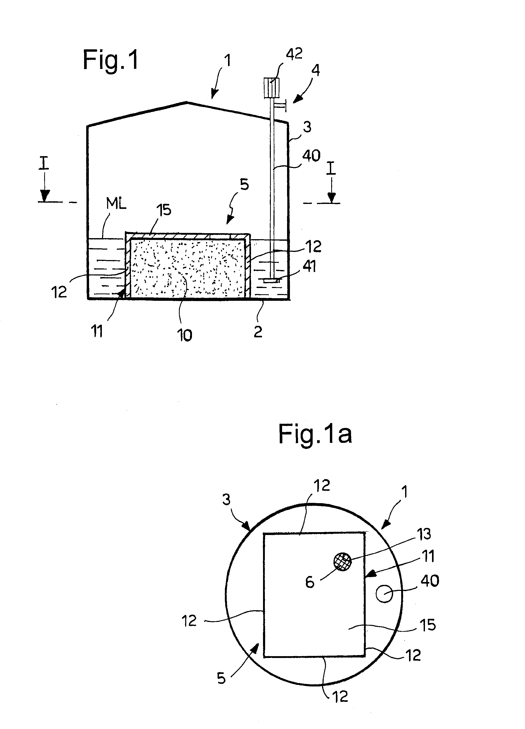
[0158]Each tank according to the present invention provided for an element consisting of a cylindrical containment body, fixed to the bottom of the tank, containing a mass of inert material of the type shown in FIGS. 1-1a.
[0159]The diameter of the containment body was 28 m and its height was 1.0 m, the total volume occupied being thus 616 m3.
[0160]A grid was used as upper side confinement on top of the inert material. The grid was welded to the lateral confinement of the containment body.
[0161]The inert material consisted of a layer of silica sand having a height of 0.6 m and a void fraction (defined as void volume divided by total volume) of 0.15. On t...
example 3
[0164]A heat storage system comprising two heat storage tanks according to the present invention was designed for satisfying the same heat storage capacity requirements of the CSP plant described in Example 1.
[0165]Each tank was equipped with the same number and type of pumps of the tanks used in the heat storage system of the state of the art.
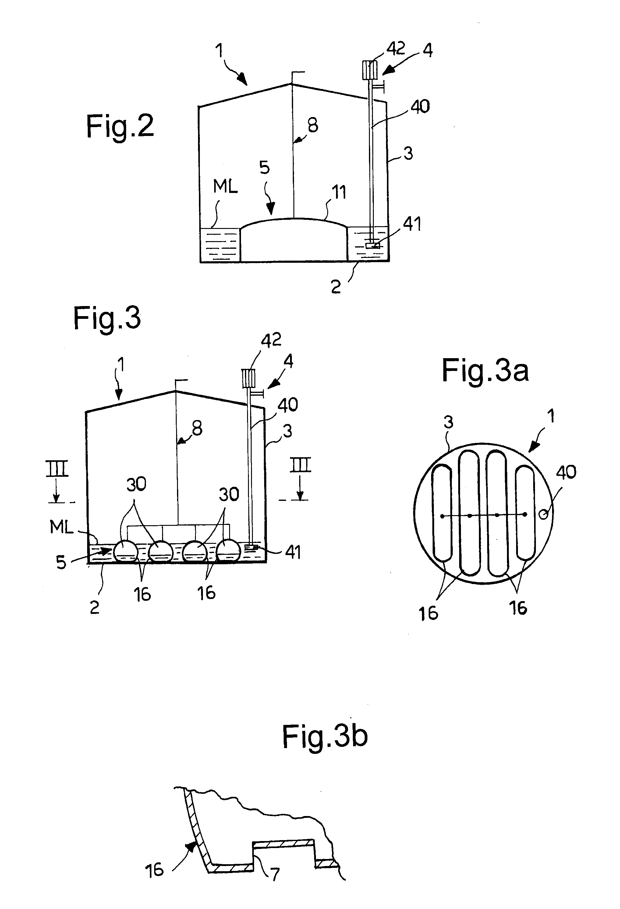
[0166]Each tank according to the present invention comprised an element placed inside the tank, fixed to bottom of the tank, consisting of a containment body filled with gaseous nitrogen. The containment body was a cylindrical tank (secondary tank) not having any opening that puts its inner volume in communication with the mass of molten salts contained in the main tank.
[0167]Nitrogen was supplied to each secondary tank by an external supply and vent system connected to the secondary tank through a pipe.
[0168]The diameter of each secondary tank was 28 m and its height was 1.0 m. The total volume occupied by each secondary tank was 616 m3 corre...
PUM
 Abstract
Description
Claims
Application Information
 - R&D
- Intellectual Property
- Life Sciences
- Materials
- Tech Scout
- Unparalleled Data Quality
- Higher Quality Content
- 60% Fewer Hallucinations
Browse by: Latest US Patents, China's latest patents, Technical Efficacy Thesaurus, Application Domain, Technology Topic, Popular Technical Reports.
© 2025 PatSnap. All rights reserved.Legal|Privacy policy|Modern Slavery Act Transparency Statement|Sitemap|About US| Contact US: help@patsnap.com