Camera system and interchangeable lens

Inactive Publication Date: 2011-05-12
PANASONIC CORP
View PDF8 Cites 8 Cited by
  • Summary
  • Abstract
  • Description
  • Claims
  • Application Information

AI Technical Summary

Benefits of technology

[0014]With this camera system, the lens controller changes the movable area of the focus lens via the focus driver depending on whether the focus lens support frame is driven by the focus driver on the basis of the position information inputted to the information input part, or the focus lens support unit is driven by the focus driver on the basis of the contrast information. Therefore, this prevents the surplus movable area that is needed in acquiring the contrast information from being used during manual imaging in which the focus lens support frame is driven on the basis of position information.
[0019]With this interchangeable lens, the lens controller changes the movable area of the focus lens via the focus driver depending on whether the focus lens support frame is driven by the focus driver on the basis of the position information inputted to the information input part, or the focus lens support unit is driven by the focus driver on the basis of the contrast information. Therefore, this prevents the surplus movable area that is needed in acquiring the contrast information from being used during manual imaging in which the focus lens support frame is driven on the basis of position information.

Problems solved by technology

Since a reflecting mirror is used with phase difference detection, however, the reflecting mirror has to be inserted into the optical path in detecting the focus point, which means that the image displayed on the liquid crystal monitor is temporarily interrupted during focusing, and this is distracting to the user.
However, with a contrast detection method, the focus lens has to be moved by an extra amount around the focus position, so if contrast detection of the conventional type is used without modification, there is not enough movable area for the focus lens, and the focus position cannot be accurately ascertained around the ends of the movable area of the focus lens.

Method used


Image

  • Camera system and interchangeable lens
  • Camera system and interchangeable lens
  • Camera system and interchangeable lens

Examples


Embodiment Construction

[0070]Embodiments of the present invention will now be described in detail through reference to the drawings.

[0071]1: Overall Configuration of Camera System

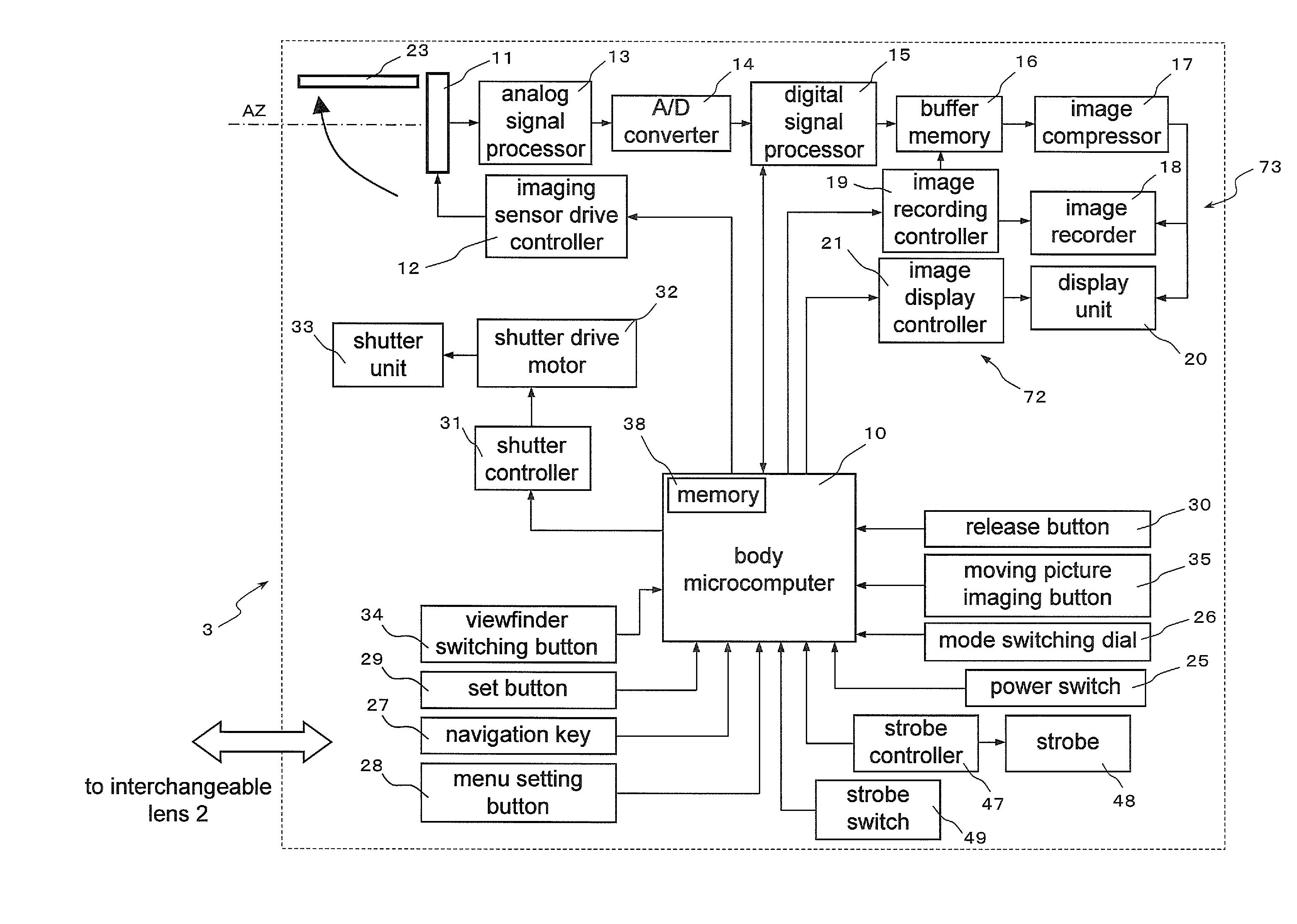
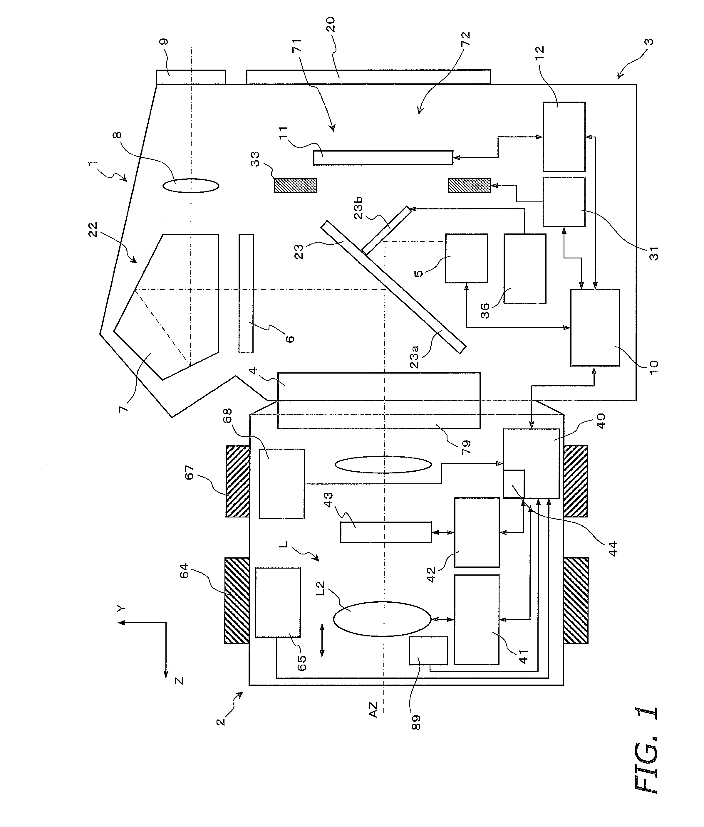
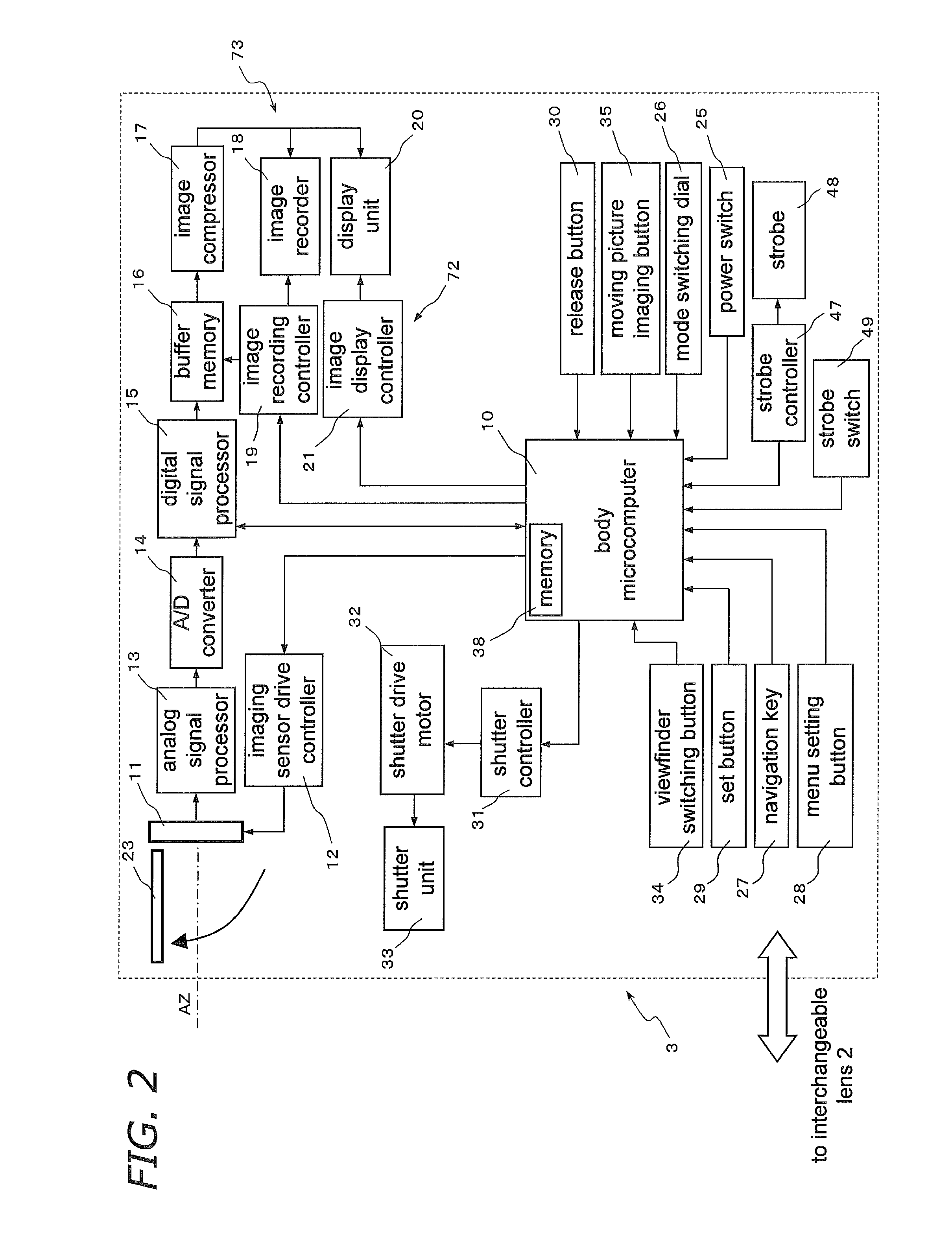
[0072]The overall configuration of a camera system 1 according to the first embodiment will be described through reference to FIGS. 1 through 3B. FIG. 1 is a block diagram of the camera system 1. FIG. 2 is a block diagram of a camera body 3. FIGS. 3A and 3B are simplified diagrams of the camera body 3.

[0073]As shown in FIG. 1, the camera system 1 is a system used in an interchangeable lens type of single lens reflex digital camera, and mainly comprises a camera body 3 having the primary function of the camera system 1, and an interchangeable lens unit 2 that is removably mounted to the camera body 3. The interchangeable lens unit 2 is mounted via a lens mount 79 to a body mount 4 provided to the front face of the camera body 3.

[0074]1.1: Camera Body

[0075]As shown in FIGS. 1 and 2, the camera body 3 mainly comprises an imaging par...


PUM


Abstract

There are provided a camera system and an interchangeable lens that are compatible with a contrast detection method. A camera system (1) has an interchangeable lens unit (2) and a camera body (3). A lens microcomputer (40) changes the movable range of a second lens group (L2) via a focus lens drive controller (41) depending on whether a second holder (61) is driven by the focus lens drive controller (41) and a focus motor (80) on the basis of angle information inputted to a zoom ring (64) of the interchangeable lens unit (2), or the second holder (61) is driven by the focus lens drive controller (41) on the basis of contrast information.

Description

TECHNICAL FIELD[0001]The present invention relates to a camera system and an interchangeable lens, and more particularly to a camera system and an interchangeable lens used in an interchangeable lens type of digital camera.BACKGROUND ART[0002]Digital single lens reflex cameras, with which an optical image of a subject is converted into an electrical image signal and outputted, have rapidly grown in popularity in recent years. With these digital single lens reflex cameras, when the user views a subject through the viewfinder, the light incident on the imaging lens (that is, the subject image) is reflected by a reflecting mirror disposed along the imaging optical path beyond the lens, which changes the optical path and sends the subject image through a pentaprism or the like to create a positive image, and guides this to an optical viewfinder. This allows the subject image that has passed through the lens to be seen through the optical viewfinder. Therefore, the position where the vie...

Claims


Application Information

Patent Timeline
IPC IPC(8): H04N5/232
CPCG02B7/023G02B7/026G02B7/102G03B3/10H04N5/23293G03B17/14H04N5/23212H04N5/23245G03B13/36H04N23/673H04N23/55H04N23/667
Inventor SANTO, TAKEOYUMIKI, NAOTOMIYATAKE, YOSHITOKUBOTA, HIROSHI
Owner PANASONIC CORP
Why Eureka
Try Eureka