
MRI involving dynamic profile sharing such as keyhole and motion correction

a dynamic profile and magnetic resonance technology, applied in the field of magnetic resonance imaging, can solve the problems of motion artifacts in the reconstructed mr image, adversely affecting image quality, and inability to acquire sufficient mr data, so as to achieve the effect of reducing motion artifacts

Inactive Publication Date: 2011-05-05
KONINKLIJKE PHILIPS ELECTRONICS NV
View PDF0 Cites 20 Cited by
  • Summary
  • Abstract
  • Description
  • Claims
  • Application Information

AI Technical Summary

Benefits of technology

[0008]Therefore, it is readily appreciated that there is a need for an improved MR device. It is consequently an object of the invention to provide an MR device that enables dynamic MRI with significantly reduced motion artifacts.
[0014]According to a preferred embodiment of the invention, the MR device is arranged to repeat steps a) and b) in order to acquire a plurality of MR data sets from the first part of k-space successively in time, to reconstruct an incomplete MR image from each acquired MR data set immediately after its acquisition, and to derive image transformation parameters from each reconstructed incomplete MR image. On the basis of these image transformation parameters, a motion correction is applied to the imaging parameters of the imaging sequence used in the succession of MR data acquisitions. The imaging parameters, such as, e.g., the strength and directions of the switched magnetic field gradients, determine the location and orientation of the FOV. The motion detected after each acquisition of a partial k-space MR data set is used in accordance with this embodiment of the invention to adapt the acquisition of the subsequent MR data sets from the first and / or second parts of k-space in order to further reduce motion-induced image artifacts.

Problems solved by technology

In a variety of MRI applications, motion of the examined object can adversely affect image quality.
Acquisition of sufficient MR data for reconstruction of an image takes a finite period of time.
Motion of the object to be imaged during that finite acquisition time typically results in motion artifacts in the reconstructed MR image.
In the case of medical MRI, motion artifacts can result for example from cardiac cycling, respiratory cycling, and other physiological processes, as well as from patient motion.
In dynamic MRI scans, the motion of the examined object during data acquisition leads to different kinds of blurring, mispositioning and deformation artifacts.
Especially in three-dimensional dynamic MRI the time required for acquisition of a single MR data set is still too long to perform an effective motion correction and to avoid motion-induced image artifacts.

Method used


Image

  • MRI involving dynamic profile sharing such as keyhole and motion correction
  • MRI involving dynamic profile sharing such as keyhole and motion correction
  • MRI involving dynamic profile sharing such as keyhole and motion correction

Examples


Embodiment Construction

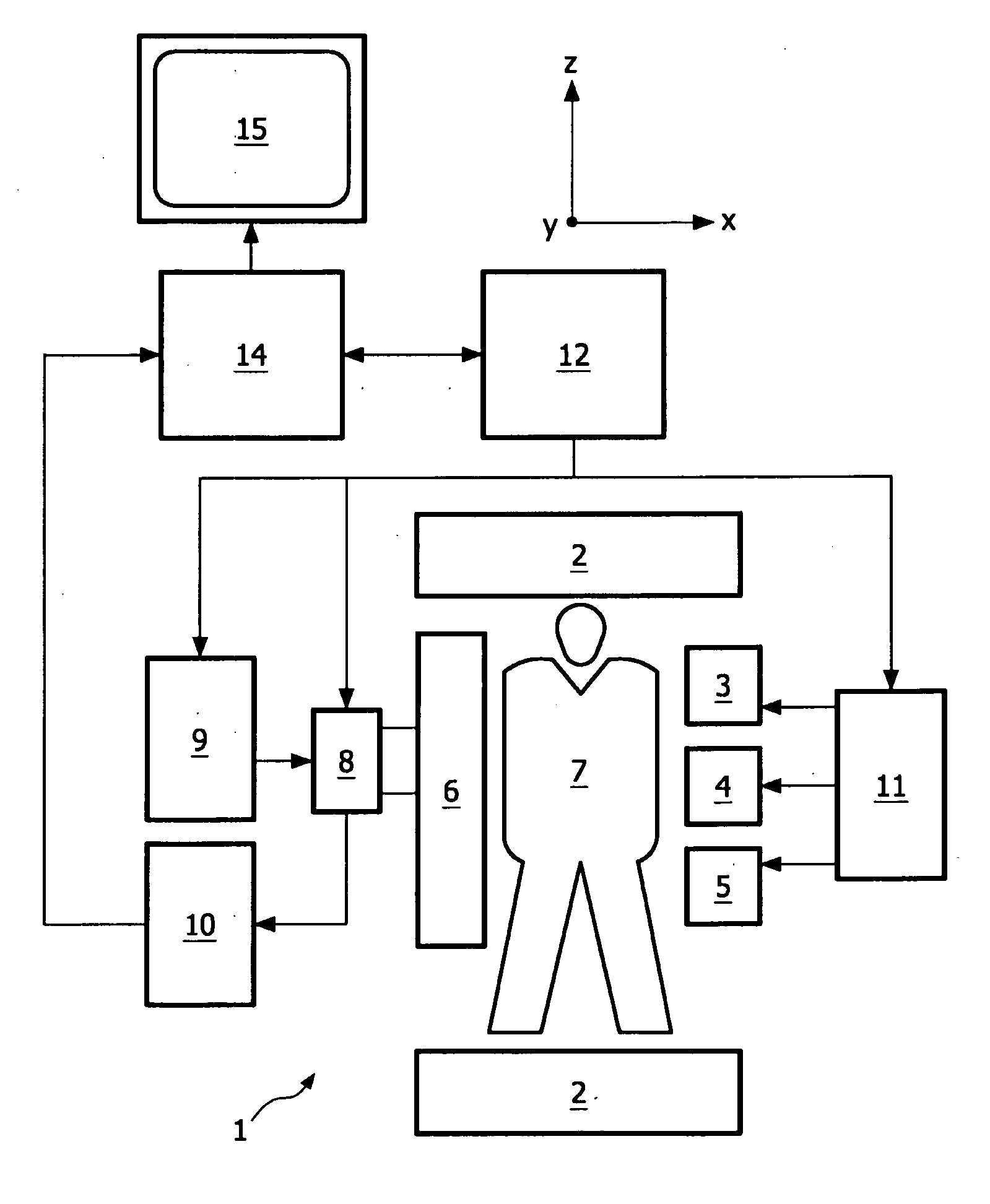
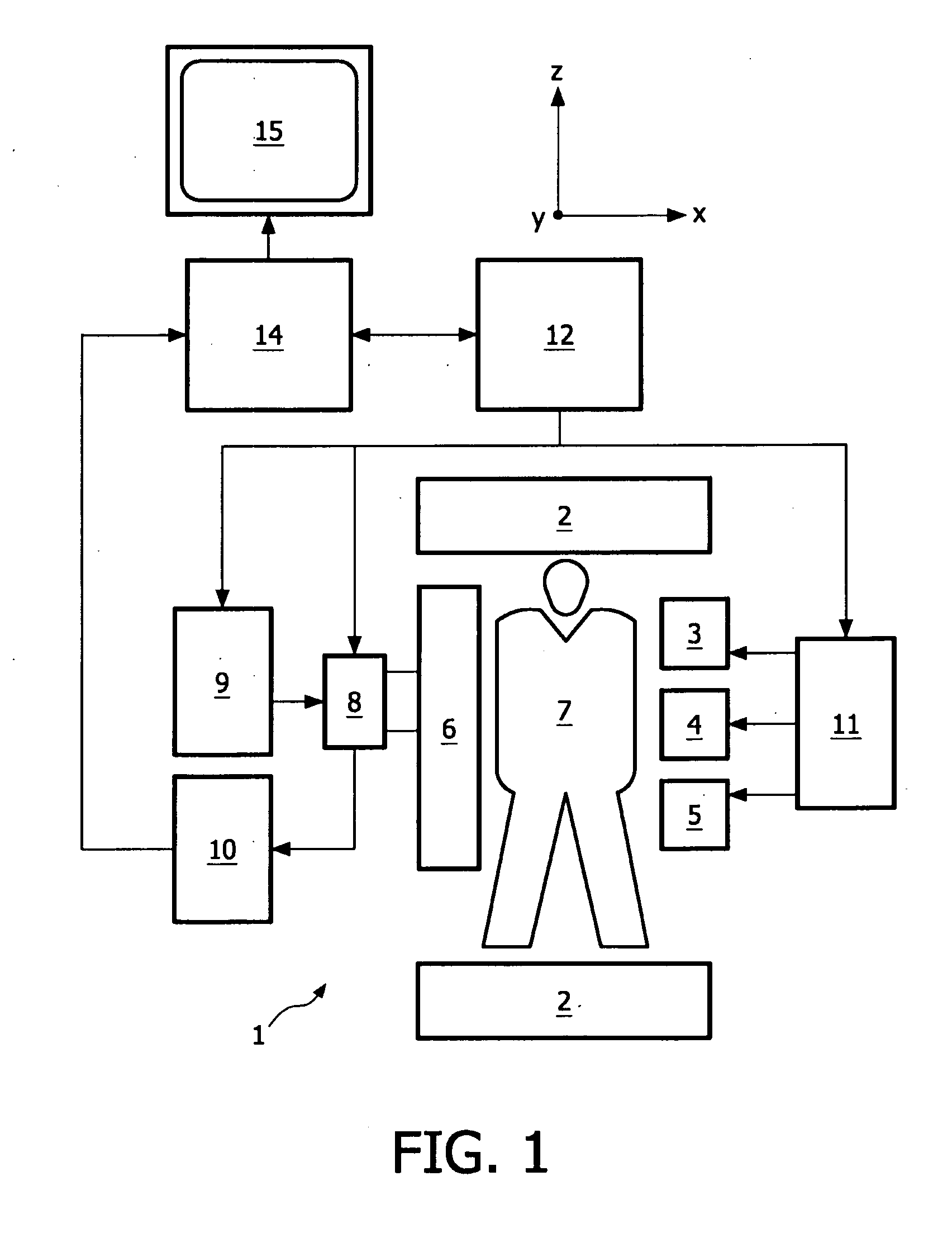
[0022]In FIG. 1 an MR imaging device 1 in accordance with the present invention is shown as a block diagram. The apparatus 1 comprises a set of main magnetic coils 2 for generating a stationary and homogeneous main magnetic field and three sets of gradient coils 3, 4 and 5 for superimposing additional magnetic fields with controllable strength and having a gradient in a selected direction. Conventionally, the direction of the main magnetic field is labeled the z-direction, the two directions perpendicular thereto the x- and y-directions. The gradient coils 3, 4 and 5 are energized via a power supply 11. The imaging device 1 further comprises an RF transmit antenna 6 for emitting radio frequency (RF) pulses to a body 7. The antenna 6 is coupled to a modulator 9 for generating and modulating the RF pulses. Also provided is a receiver for receiving the MR signals, the receiver can be identical to the transmit antenna 6 or be separate. If the transmit antenna 6 and receiver are physical...


PUM


Abstract

The invention relates to a device and to a method for magnetic resonance imaging (MRI) of a body. It is an object of the invention to provide a technique that enables dynamic profile sharing with significantly reduced motion artifacts. The method of the (such as keyhole) invention comprises the following steps: a) acquiring an MR data set (21) from an incomplete first part of k-space (C) by subjecting the body to an imaging sequence of RF pulses and switched magnetic field gradients; b) reconstructing an incomplete MR image (31) from the MR data set (21) acquired in step a) and deriving image transformation parameters describing motion of the body from the reconstructed incomplete MR image (31), -c) acquiring an MR data set (24) from an incomplete second part of k-space (P), which second part (P) is different from the first part (C) sampled in step a); d) applying a motion correction (40) to at least one of the MR data sets (21, 24) acquired in steps a) and c) according to the image transformation parameters derived in step b); e) reconstructing a final MR image (81) from a combination (71) of the motion-corrected MR data sets (61, 64).

Description

FIELD OF THE INVENTION[0001]The invention relates to a device for magnetic resonance (MR) imaging of a body placed in an examination volume.[0002]Furthermore, the invention relates to a method for magnetic resonance imaging (MRI) and to a computer program for an MR device.BACKGROUND OF THE INVENTION[0003]In MRI pulse sequences consisting of RF pulses and switched magnetic field gradients are applied to an object (a patient) placed in a homogeneous magnetic field within an examination volume of an MR device. In this way, phase and frequency encoded magnetic resonance signals are generated, which are scanned by means of RF receiving antennas in order to obtain information from the object and to reconstruct images thereof. Since its initial development, the number of clinically relevant fields of application of MRI has grown enormously. MRI can be applied to almost every part of the body, and it can be used to obtain information about a number of important functions of the human body. ...

Claims


Application Information

Patent Timeline
IPC IPC(8): A61B5/055G06K9/00
CPCG01R33/561G01R33/5619G01R33/5676G01R33/56509G01R33/56308
Inventor BECK, GABRIELE MARIANNE
Owner KONINKLIJKE PHILIPS ELECTRONICS NV
Learn More