
Hybrid drive train for a motor vehicle and method for operating the hybrid drive train

a hybrid drive and motor vehicle technology, applied in the direction of electric propulsion mounting, dynamo-electric gear control, gearing, etc., can solve the problems of less favorable consumption and emissions of driving and in particular constant driving under fully or partially electrically generated propulsion, increased weight of the vehicle, electric driving, etc., to achieve the effect of less energy and simplified engagement of a new gear

Inactive Publication Date: 2011-04-28
ZF FRIEDRICHSHAFEN AG
View PDF12 Cites 49 Cited by
  • Summary
  • Abstract
  • Description
  • Claims
  • Application Information

AI Technical Summary

Benefits of technology

[0015]The purpose of the present invention is to indicate a hybrid drive train which, while improving driving performances and preserving the comfort of an automatic transmission, enables consumption and emissions to be reduced and, as regards structural complexity, weight and costs, is more favorable compared with the known hybrid drive trains.

Problems solved by technology

Disadvantageously, however, driving and in particular constant driving under fully or partially electrically generated propulsion are less favorable in relation to consumption and emissions compared with propulsion powered purely by an internal combustion engine, provided that the internal combustion engine is operated in a rotational speed range which favors low consumption.
Another disadvantage of hybrid drive trains is that electric driving takes place by the feeding of originally fossil energy into the battery and its later recovery, processes which respectively involve significant losses.
In addition, owing to the low energy density (around 5 Wh / kg) of the energy accumulator the weight of the vehicle is increased, which affects the consumption adversely.
Furthermore, the structural complexity and hence the production and assembly costs of hybrid drive trains are high.

Method used


Image

  • Hybrid drive train for a motor vehicle and method for operating the hybrid drive train
  • Hybrid drive train for a motor vehicle and method for operating the hybrid drive train
  • Hybrid drive train for a motor vehicle and method for operating the hybrid drive train

Examples


Embodiment Construction

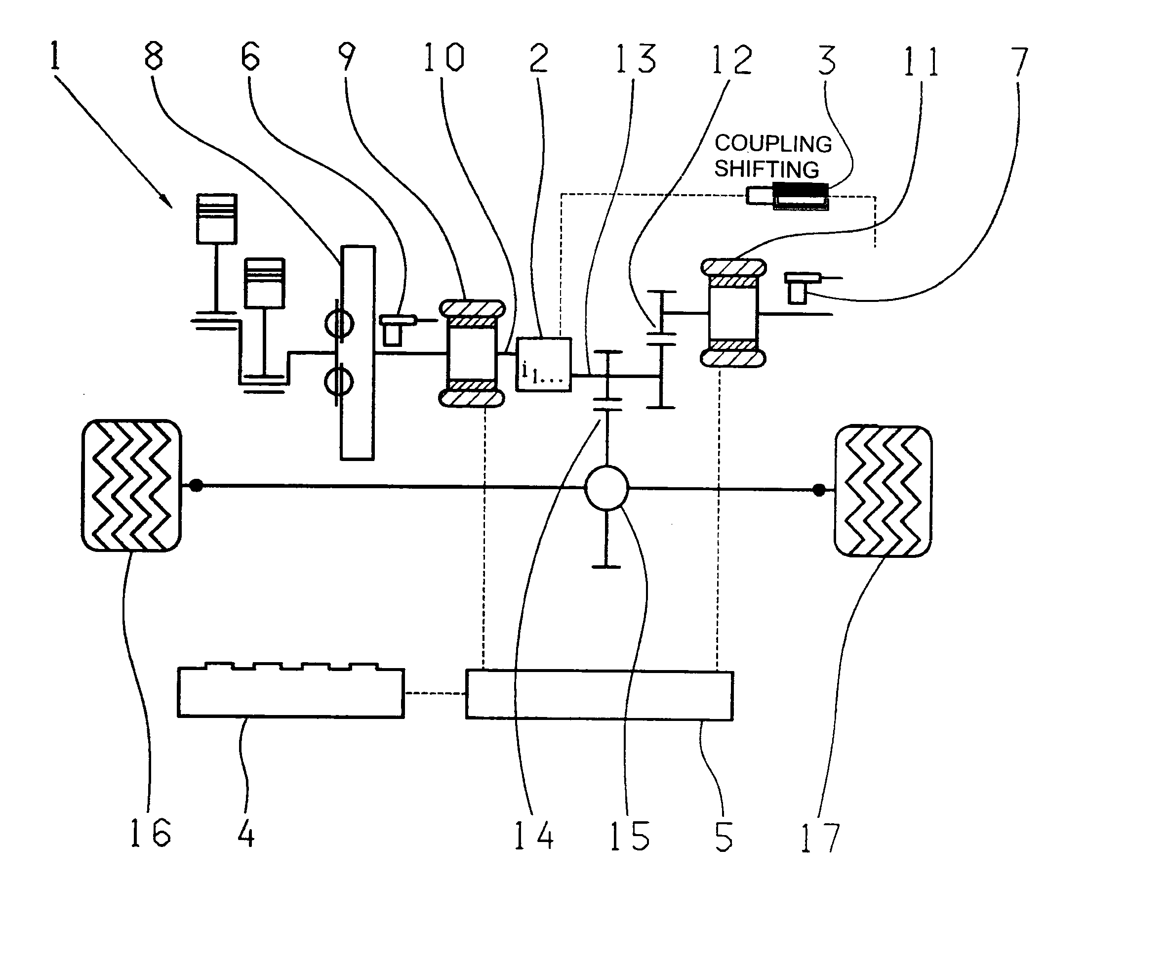
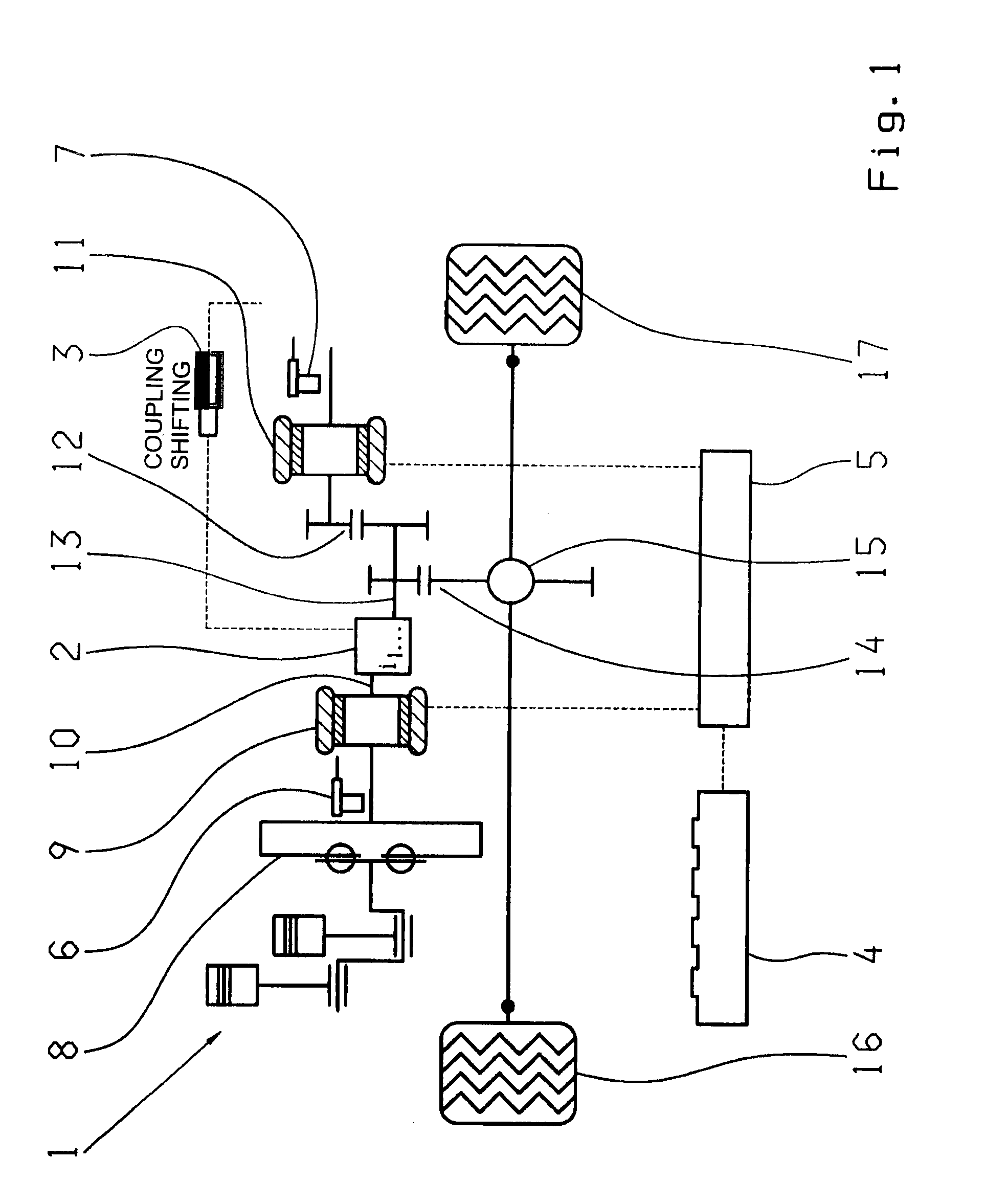
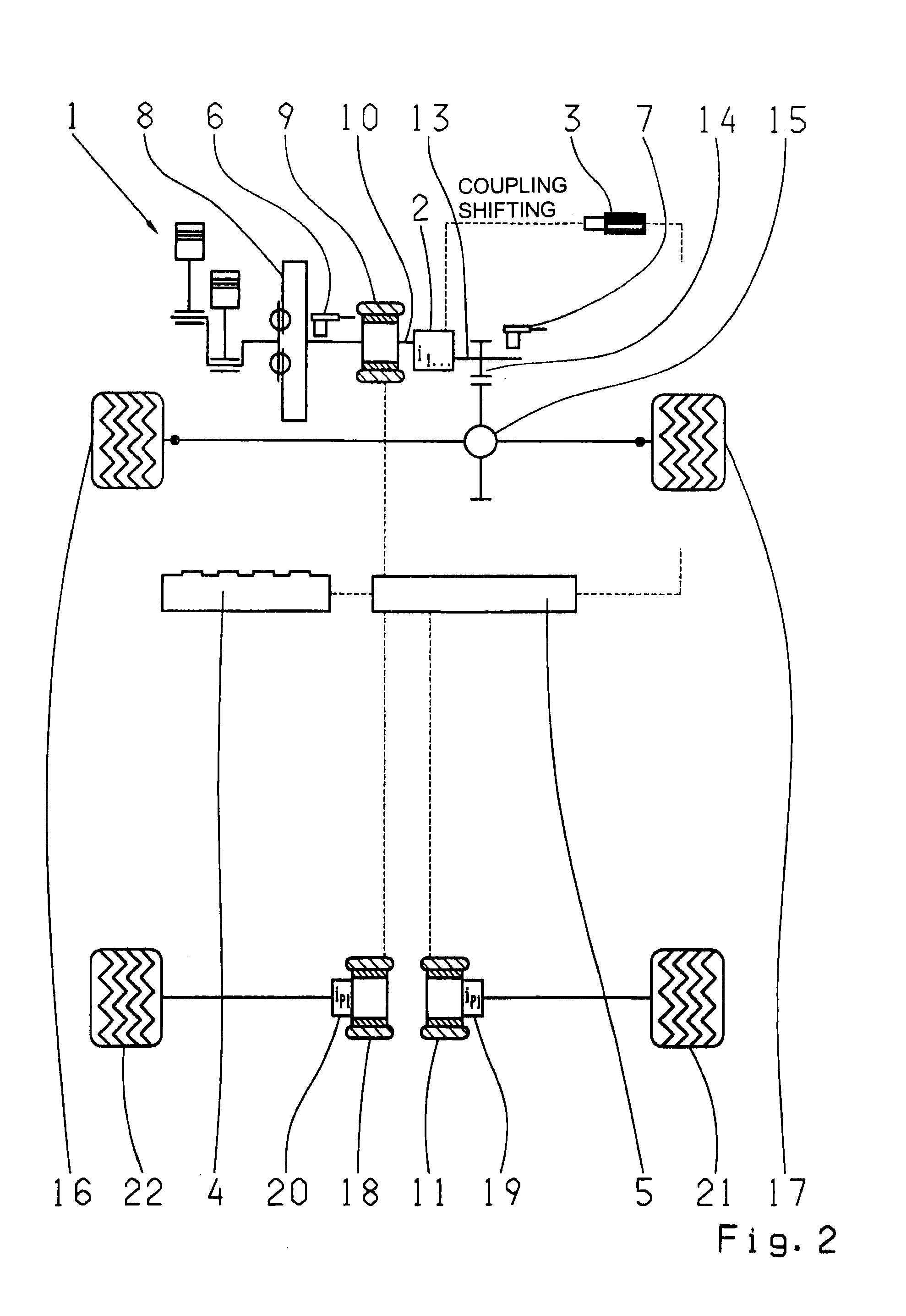
[0052]FIG. 1 shows a hybrid drive train comprising an internal combustion engine 1 mounted transversely at the front, two electric machines 9, 11, a transmission 2 with a plurality of gears, an electric-motor-driven shift actuator 3, double-layer condensers 4 as an energy storage device, and a control unit 5 with power electronics and speed sensors 6, 7 arranged ahead of and behind the transmission 2.

[0053]In the example shown in FIG. 1 the internal combustion engine 1 is connected, via a torsion damper 8, to the first electric machine 9, which is connected rotationally fixed to the transmission input shaft 10 of the transmission 2. According to the invention, the second electric machine is connected, via a spur gear arrangement 12, to the transmission output shaft 13 of the transmission 2.

[0054]Furthermore, the transmission output shaft 13 of the transmission 2 is connected by a spur gear arrangement 14 to a differential 15 for distributing the drive torque to the two front wheels ...


PUM


Abstract

A hybrid drive train for a motor vehicle which comprises an combustion engine, at least two electric machines, a multi-gear transmission with transmission input and output shafts, a shift actuator, at least one energy storage device and a control unit arranged such that the combustion engine and the rotor of the first electric machine are connected to the transmission input shaft, and the transmission output shaft is connected either permanently or via a gearwheel arrangement or a chain or toothed-belt drive mechanism to at least one wheel or to a differential of a first vehicle axle. The rotor of the second electric machine is connected either permanently or via a chain or toothed-belt drive mechanism, either to at least one wheel or to a differential of the first vehicle axle, or to at least one wheel or to a differential of a second vehicle axle.

Description

[0001]This application is a National Stage completion of PCT / EP2009 / 056422 filed May 27, 2009, which claims priority from German patent application serial no. 10 2008 002 381.7 filed Jun. 12, 2008.FIELD OF THE INVENTION[0002]The present invention relates to a hybrid drive train for a motor vehicle. In addition the invention relates to a method for operating the hybrid drive train according to the invention.BACKGROUND OF THE INVENTION[0003]From the prior art hybrid vehicles are known, which comprise a hybrid transmission having a basic transmission and a hybrid assembly, the hybrid assembly as a rule replacing a hydrodynamic torque converter. In addition to the internal combustion engine they comprise at least one electric motor or electric machine, which can operate as a motor or as a generator depending on the operating situation. In series hybrid vehicles, a generator is driven by the internal combustion engine and the generator then supplies electrical energy to the electric moto...

Claims


Application Information

Patent Timeline
Patent Type & Authority Applications(United States)
IPC IPC(8): B60W20/00B60K6/42B60W10/10B60W10/08
CPCB60K1/02Y10T477/347B60K6/485B60K6/52B60K6/547B60K2006/541B60L2240/421B60L2240/423B60W10/08B60W20/00B60W2710/0644B60W2710/081B60W2710/083F16H3/126Y02T10/6226Y02T10/6234Y02T10/6265Y02T10/642B60K6/442Y02T10/62Y02T10/64B60K2006/268B60W20/30
Inventor ZIEMER, PETER
Owner ZF FRIEDRICHSHAFEN AG
Learn More