
Sensor scan drivers, flat panel displays with built-in touch screen including such a sensor scan driver, and methods of driving such flat panel displays

a technology of sensor scan and driver, which is applied in the direction of pulse generator, pulse technique, instruments, etc., can solve the problems of increasing manufacturing cost, increasing thickness of fpd, and deteriorating entire optical characteristics of fpd, so as to improve the optical sensitivity of photodiodes and improve the characteristics of built-in touch screens

Active Publication Date: 2011-04-28
SAMSUNG DISPLAY CO LTD
View PDF8 Cites 36 Cited by
  • Summary
  • Abstract
  • Description
  • Claims
  • Application Information

AI Technical Summary

Benefits of technology

[0014]It is therefore a separate feature of an embodiment to provide a sensor scan driver including a transmission gate unit adapted to stably change a voltage range of sensor scan signals supplied from a shift register to output a voltage range to improve the optical sensitivity of the photodiodes and, as a result, improve characteristics of the built-in touch screen.

Problems solved by technology

When the display panel and the touch screen panel are additionally provided and the touch screen panel is attached onto the display panel, the entire optical characteristic of the FPD may deteriorate, manufacturing cost increases, and the thickness of the FPD increases.
When such a level shifter is employed, during a transition period where a level of first and second input signals may rise from a low level to a high level or fall from a high level to a low level, leakage current may be generated and power consumption may increase.
As a result of such leakage current, a circuit may erroneously operate and an output signal generated therefrom may be unstable.
More particularly, e.g., when a sensor scan driver employs such a common level shifter driving signals may not be stably supplied to photodiodes of the touch screen panel.

Method used


Image

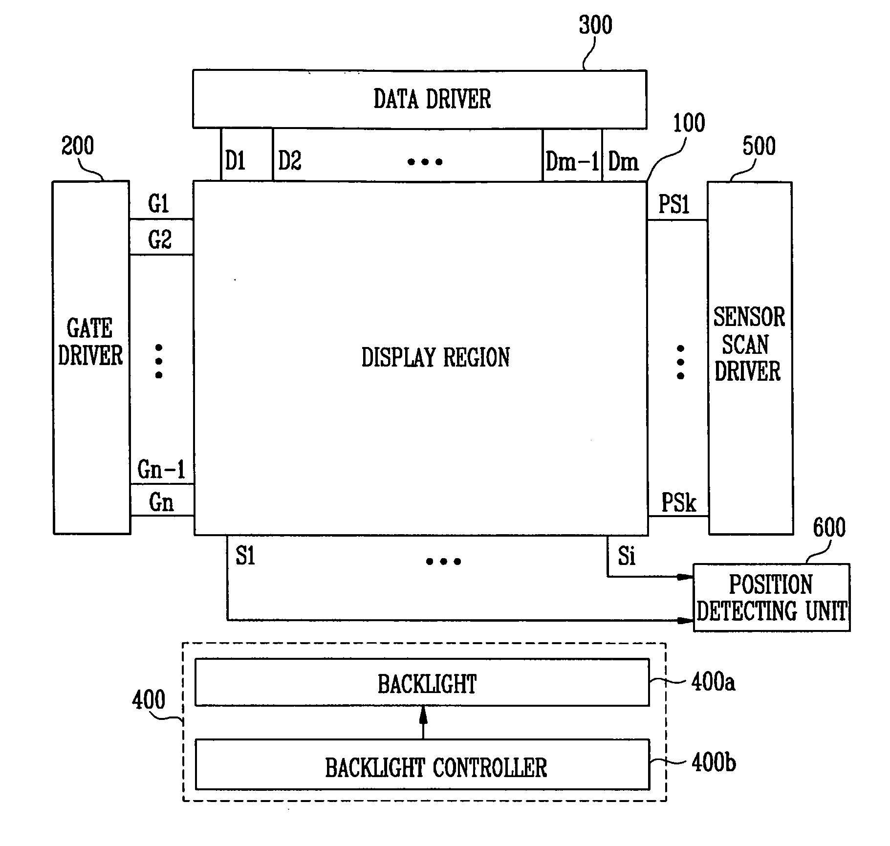
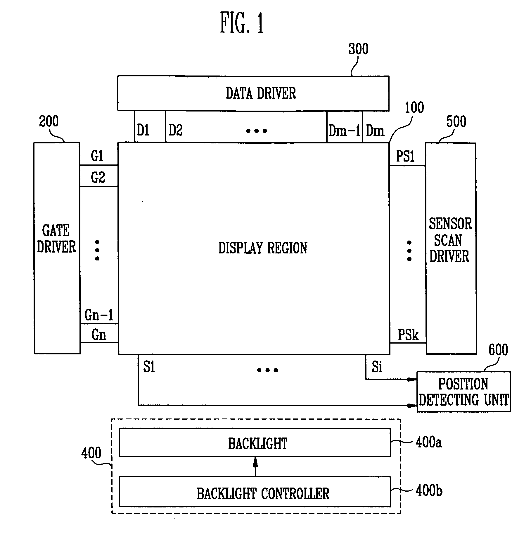
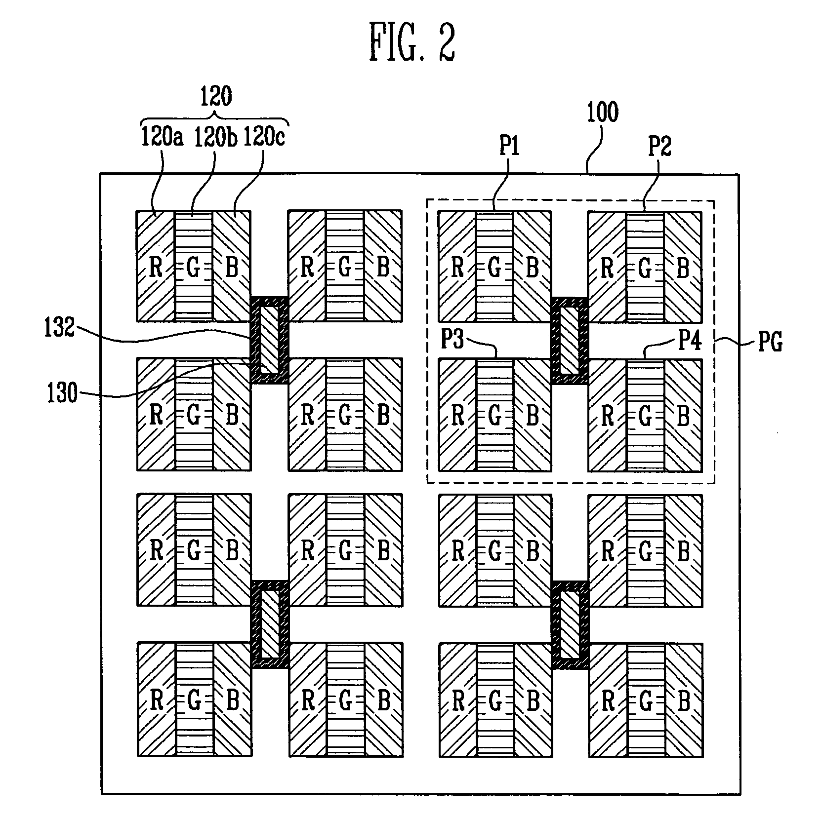
  • Sensor scan drivers, flat panel displays with built-in touch screen including such a sensor scan driver, and methods of driving such flat panel displays
  • Sensor scan drivers, flat panel displays with built-in touch screen including such a sensor scan driver, and methods of driving such flat panel displays
  • Sensor scan drivers, flat panel displays with built-in touch screen including such a sensor scan driver, and methods of driving such flat panel displays

Examples


Embodiment Construction

[0035]Korean Patent Application No. 10-2009-0100643, filed on Oct. 22, 2009, in the Korean Intellectual Property Office, and entitled: “Sensor Scan Driver and Flat Panel Display with a Built-in Touch Screen Having the Same” is incorporated by reference herein in its entirety.

[0036]Exemplary embodiments will now be described more fully hereinafter with reference to the accompanying drawings; however, they may be embodied in different forms and should not be construed as limited to the embodiments set forth herein. Rather, these embodiments are provided so that this disclosure will be thorough and complete, and will fully convey the scope of the invention to those skilled in the art.

[0037]In the drawing figures, the dimensions of elements may be exaggerated for clarity of illustration. It will also be understood that when an element is referred to as being “on” another element, it can be directly on the other element, or intervening elements may also be present. Further, it will be un...


PUM


Abstract

A sensor scan driver may include a shift register unit for driving photodiodes, a transmission gate unit for changing a voltage range of sensor scan signals generated by the shift register unit, and a buffer unit for supplying the sensor scan signals supplied from the transmission gate unit to the photodiodes, wherein the transmission gate unit includes first and second transmission gates, each including an electrode adapted to receive an output signal of the shift register unit, another electrode adapted to receive the inverted output signal of the shift register unit, an input terminal coupled to first and second power sources, respectively, and an output terminal coupled to an output terminal of the transmission gate unit.

Description

BACKGROUND[0001]1. Field[0002]Embodiments relate to a flat panel display (FPD) with a built-in touch screen and a method of driving the same. More particularly, embodiments relate to a sensor scan driver capable of supplying stable driving signals to photodiodes for performing the function of a touch screen and a FPD with a built-in touch screen including the same.[0003]2. Description of the Related Art[0004]A touch screen is provided on the top surface of an image display so that a person may select instruction contents displayed on the screen of the image display by a hand or an object and contacts the hand or the object. The touch screen grasps a contact position and the image display receives the content instructed by the contact position as an input signal to be driven in accordance with the input signal.[0005]Since the image display having the touch screen does not need an additional input device, e.g., a keyboard and a mouse, coupled to the image display to be driven, the use...

Claims


Application Information

Patent Timeline
IPC IPC(8): G06F3/042H03B1/00
CPCG06F3/042G06F3/0412G09G3/3677G09G2310/0286G09G2310/0291G09G2354/00G09G2360/14G09G2360/144G02F1/13338G09G3/3674G06F3/04166
Inventor JEON, MU-KYUNGKIM, SANG-UKHWANG, HEE-CHULYOSHIMURA, HIDEOPARK, JIN-WOO
Owner SAMSUNG DISPLAY CO LTD
Learn More