
Light emitting apparatus

Inactive Publication Date: 2011-04-28
GIO OPTOELECTRONICS CORP
View PDF6 Cites 18 Cited by
  • Summary
  • Abstract
  • Description
  • Claims
  • Application Information

AI Technical Summary

Benefits of technology

[0011]In view of the foregoing subject, an objective of the invention is to provide a light emitting apparatus with good protection for preventing it from affecting by the external objects so as to remain the lighting efficiency and extend its lifetime.
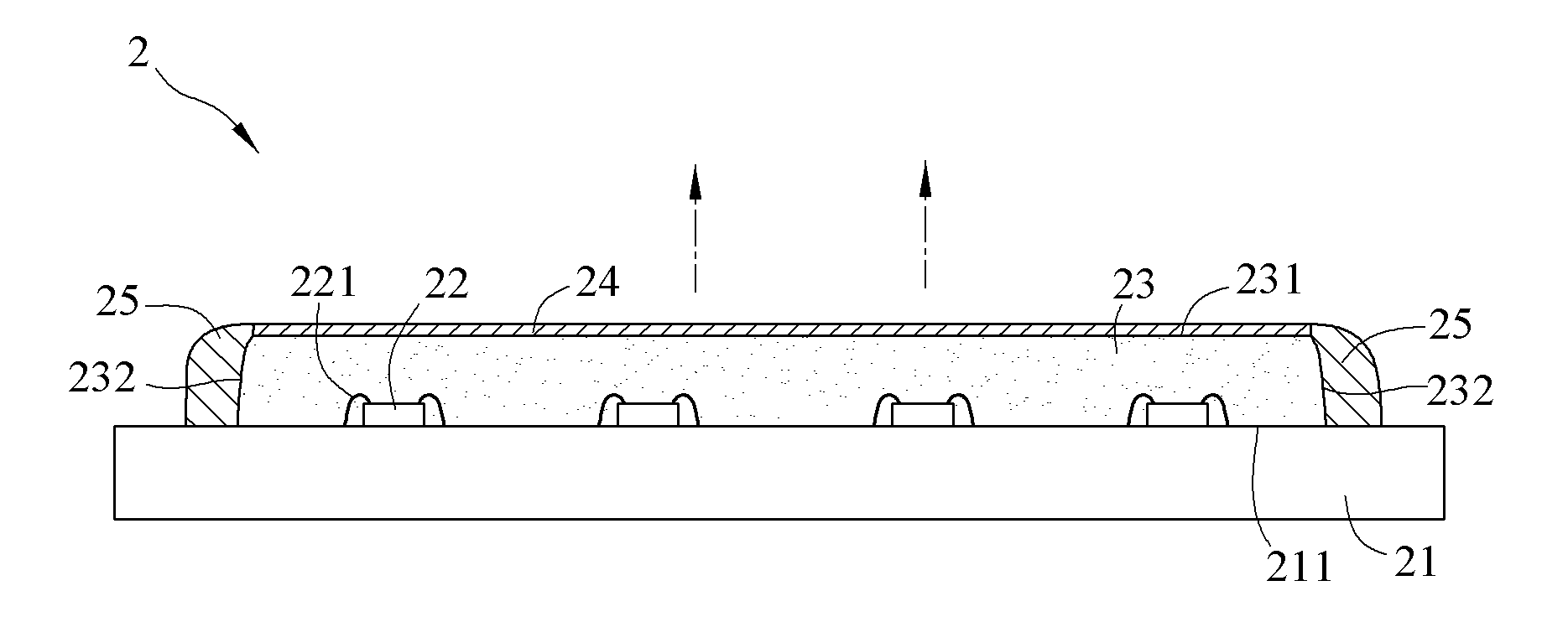
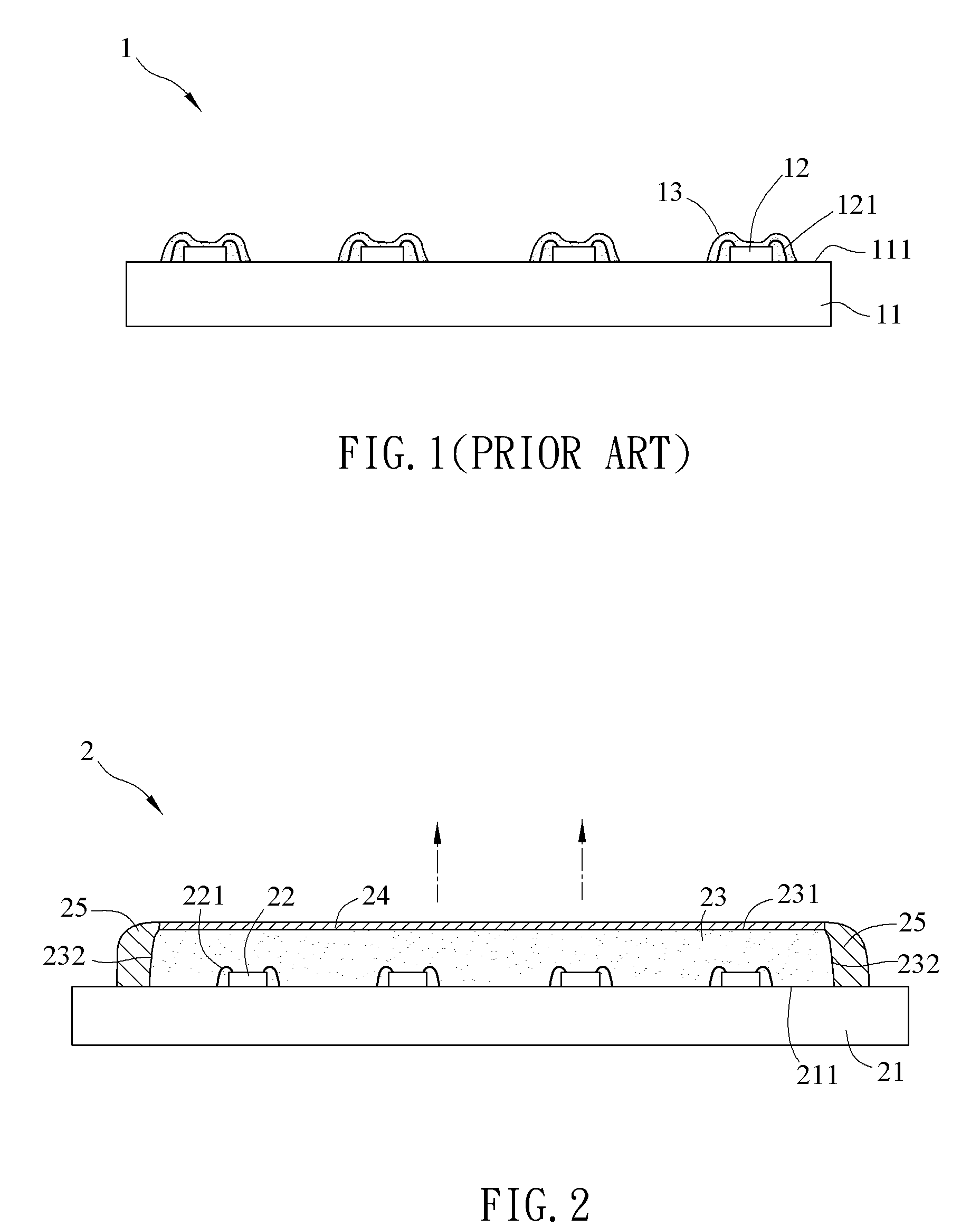
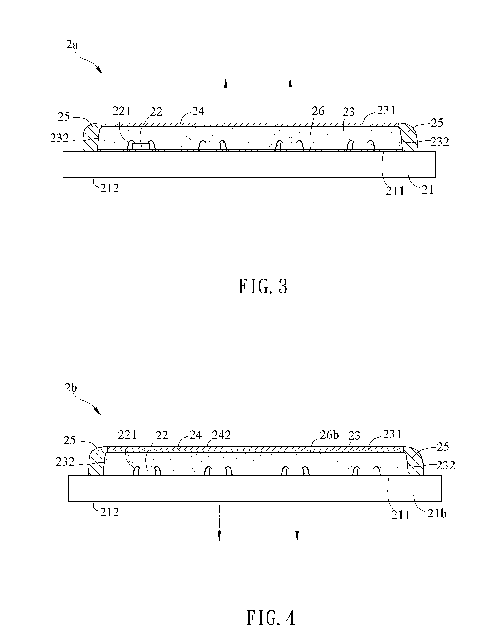
[0021]As mentioned above, the light emitting apparatus of the invention is configured with a cover sheet disposed on the top surface of the sealant and a protecting material disposed at the side surface of the sealant, and the protecting material is connected with the cover sheet and the substrate. Accordingly, the cover sheet and protecting material can tightly cover the sealant so as to prevent the sulfide, moistures or dusts in the air from entering into the light emitting apparatus, thereby avoiding the reaction of silver and sulfide, oxidization of moistures, or pollution of dusts. Thus, the lighting efficiency of the light emitting apparatus can be maintained, and the short circuit caused by the oxidization can be prevented so as to extend the lifetime of the product.

Problems solved by technology

However, the chemical structure of silica gel is not strong enough and it is hydrophilic, so the conventional sealant 13 can not provide a good protection.
If the moistures enter the light emitting apparatus 1, the metal portions therein may be oxidized to form rusts, which will cause short circuit or damage.

Method used


Image

  • Light emitting apparatus
  • Light emitting apparatus
  • Light emitting apparatus

Examples


Embodiment Construction

[0029]The present invention will be apparent from the following detailed description, which proceeds with reference to the accompanying drawings, wherein the same references relate to the same elements.

[0030]FIG. 2 is a cross-sectional diagram of a light emitting apparatus according to an embodiment of the present invention. Referring to FIG. 2, a light emitting apparatus 2 includes a substrate 21, at least a LED (light-emitting diode) die 22, a sealant 23, a cover sheet 24, and a protecting material 25. The light emitting apparatus 2 of the invention can be applied to, for example but not limited to, illumination devices, indicators of information, communication and consuming electronic products, backlight modules, display devices, or media boards.

[0031]To be noted, the amount and arrangement of the LED dies 22 of the light emitting apparatus 2 are not limited. In this embodiment, the light emitting apparatus 2 includes four LED dies 22, which are arranged linearly in one dimension...


PUM


Abstract

A light emitting apparatus includes a substrate, at least one LED (light-emitting diode) die, a sealant, a cover sheet and a protecting material. The LED die is disposed on the substrate. The sealant covers the LED die and has a top surface and a side surface. The cover sheet is disposed on the top surface of the sealant. The protecting material is disposed at the side surface, and connected with the cover sheet and the substrate. Accordingly, the light emitting apparatus can prevent from moisture or gas that may affect the luminous efficiency thereof, thereby extending the lifetime of the light emitting apparatus.

Description

CROSS REFERENCE TO RELATED APPLICATIONS[0001]This Non-provisional application claims priority under 35 U.S.C. §119(a) on Patent Application No(s). 098136237 filed in Taiwan, Republic of China on Oct. 26, 2009, the entire contents of which are hereby incorporated by reference.BACKGROUND OF THE INVENTION[0002]1. Field of Invention[0003]The present invention relates to a light emitting apparatus and, in particular, to a light emitting apparatus having LED (light-emitting diode).[0004]2. Related Art[0005]LED (light-emitting diode) is a light emitting component made of semiconductor materials. It has two electrodes, and when a very small voltage is applied between these electrodes, the electron and holes may combine to transform the residual energy and then emit light.[0006]Differing from the conventional lamp, the LED is a cold light illumination device, which has the advantages of low power consumption, long lifetime, no lamp warm-up time, fast response, etc. In addition, the LED is sm...

Claims


Application Information

Patent Timeline
IPC IPC(8): H01L33/60
CPCH01L25/0753H01L33/56H01L2224/48091H01L2224/48247H01L2924/1815H01L2924/00H01L2924/181H01L2924/00014H01L2924/00012
Inventor LIAO, KUANG-CHIANG
Owner GIO OPTOELECTRONICS CORP
Learn More