
Electrowetting sample presentation device for matrix-assisted laser desorption/ionization mass spectrometry and related methods

a matrix-assisted laser and sample preparation technology, which is applied in the field of sample preparation devices and methods, can solve the problems of significant variations in peak intensity, resolution and mass accuracy, and the severe limitation of present-day maldi-tof-ms sample supports with respect to liquid sample volume,

Inactive Publication Date: 2011-04-28
STRATOS BIOSYST
View PDF7 Cites 19 Cited by
  • Summary
  • Abstract
  • Description
  • Claims
  • Application Information

AI Technical Summary

Benefits of technology

[0016]It is an object of the present invention to provide a sample presentation device for matrix-assisted laser desorption / ionization mass spectrometry which is optimal with respect to receipt and subsequent positioning of a liquid sample drop.
[0017]It is a further object of the present invention to provide a sample presentation device for matrix-assisted laser desorption / ionization mass spectrometry which is optimal with respect to confining the co-deposition of analytes and matrix.
[0018]It is another object of the present invention to provide a sample presentation device for matrix-assisted laser desorption / ionization mass spectrometry so as to facilitate the homogeneous co-deposition of analytes and matrix.

Problems solved by technology

Present day MALDI-TOF-MS sample supports suffer from a severe limitation with respect to the liquid sample volume which may be applied to the support.
Unfortunately, even small volumes of less than 3.0 μL are known to result in sample heterogeneity, which gives rise to significant variations in peak intensity, resolution and mass accuracy when focusing the laser on different regions of the dried-droplet (Strupat, K.; Karas, M.; Hillenkamp, F.
Consequently, only a few hundred samples can be analyzed per instrument per day, and automated data acquisition is often precluded.
Furthermore, many samples contain detergents and salts that interfere with mass spectral analyses and must be removed.
However, the use of either ZipTips® or home-made micro-columns is time consuming, adds considerable cost, has proven difficult to automate and often affords only moderate (40 to 60%) recoveries of sample material.
Consequently, many of the difficulties outlined above regarding sample heterogeneity remain unaddressed.
A further limitation associated with the use of the Anchor Chip™ is the requirement that the volume of liquid sample applied to each anchor be limited to from 0.5 to 3.0 μL (No. 1 of Eleven General Rules for Sample Preparation on Anchor Chip™ Targets).
Therefore, although still representing an improvement of sorts, the Anchor Chip™ suffers many of the same limitations associated with other present day MALDI-TOF-MS sample supports.
Collectively, present day MALDI-TOF-MS sample supports suffer from a severe sample volume limitation, in that they are incompatible with sample volumes in excess of 3 μL.
Furthermore, even volumes as small as 3 μL can prove problematic owing to sample heterogeneity when the dried-droplet approach is utilized.
Although the Anchor Chip™ addresses some of the problems associated with sample heterogeneity by reducing the sample spot size, it suffers from the same liquid sample volume constraints as other present day sample supports.
Charge accumulates at the liquid-solid interface, leading to an increase in surface wettability and a concomitant decrease in the liquid-solid contact angle.
Never-the-less, the aforementioned report failed to address the many limitations enumerated above, in that the manipulation of volumes greater than 0.5 μL was not addressed.

Method used


Image

  • Electrowetting sample presentation device for matrix-assisted laser desorption/ionization mass spectrometry and related methods
  • Electrowetting sample presentation device for matrix-assisted laser desorption/ionization mass spectrometry and related methods
  • Electrowetting sample presentation device for matrix-assisted laser desorption/ionization mass spectrometry and related methods

Examples


example 1

[0092]The details of the stepwise fabrication of an electrowetting-on-dielectric apparatus of the present invention follow:

[0093]The surface of a 4″ silicon wafer was exposed to wet O2 / N2 at 1045° C. for 45 min to prepare a Thermal Oxide (2500 Å) insulator film.

[0094]The first metal conductive layer (control electrode elements and interconnects), comprised of 60 Å of Ti / W, 300 Å of Au and 60 Å of Ti / W was sputtered onto the Thermal Oxide surface.

[0095]Photoresist was spin-coated and patterned by contact printing to define the electrode pattern. The metal conductive layer was wet etched at room temperature employing the following sequence: (1) 30% H2O2 in TFA for 90 sec; (2) 30% H2O2 for 30 sec; and (3) 30% H2O2 in TFA for 90 sec.

[0096]Photoresist was stripped using reagent EKC830 for 10 min followed by reagent AZ300 for 5 min. The wafers were rinsed in deionized water and dried in a vacuum spinner.

[0097]Unstressed silicon nitride (dielectric, 1000 Å) was deposited by PECVD (Plasma E...

example 2

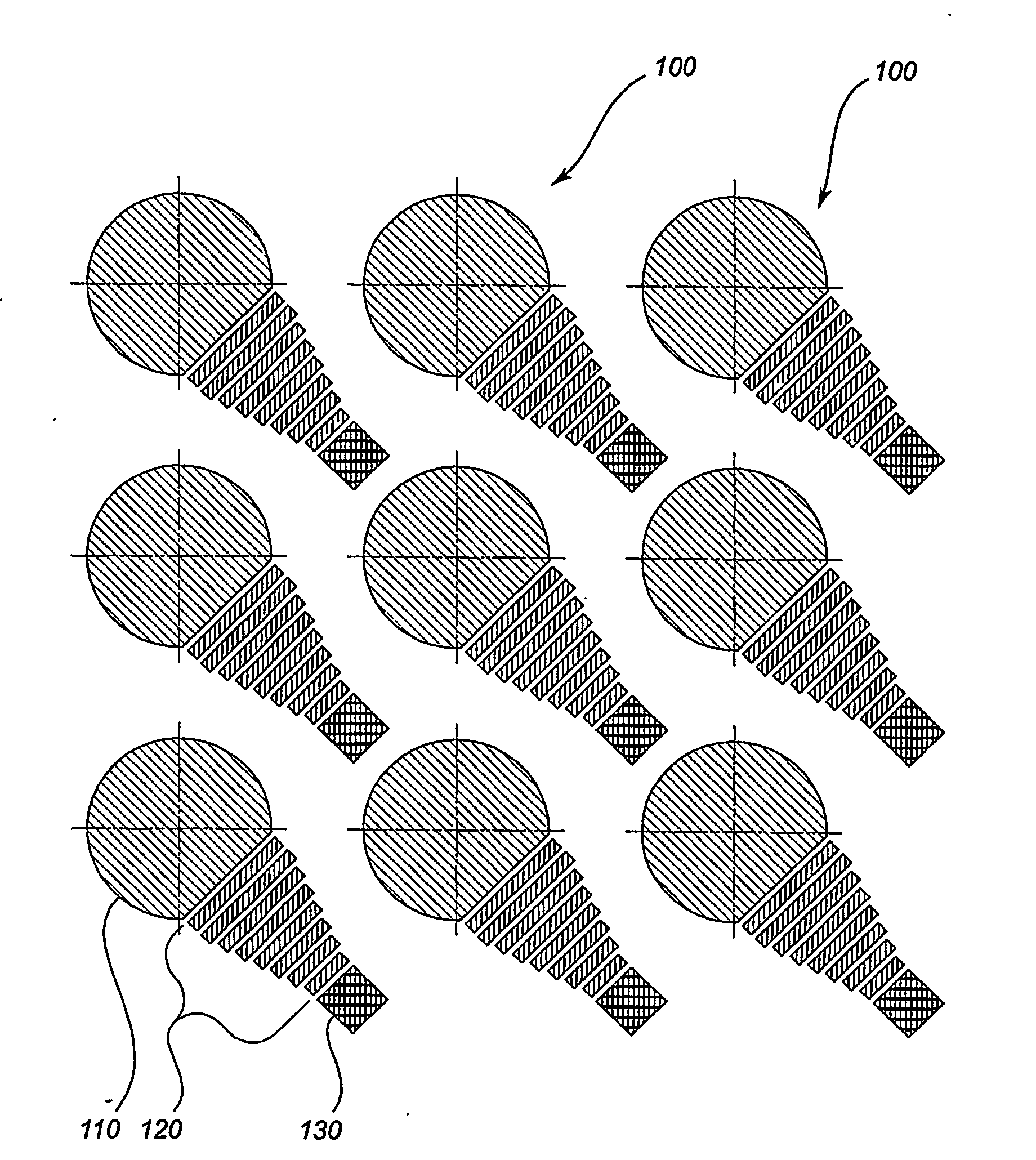
[0105]An electrowetting-on-dielectric sample presentation device of the present invention was fabricated as described in the example immediately above. One sample presentation element of the device is pictured in FIG. 7B. When a 10 μL droplet containing 2,4-dihydroxybenzoic acid matrix (10%, w / v) in water was applied to the surface of the device with all electro-wettable zones actuated (hydrophilic), the droplet initially filled the lower three electro-wettable zones. As the droplet was allowed to evaporate over the course of 30 minutes, the lower electro-wettable zones were sequentially deactivated from bottom to top thereby confining the droplet to the upper-most electro-wettable zone. Finally, when the droplet dried, the field of matrix crystals shown in FIG. 7B was obtained.


PUM


Abstract

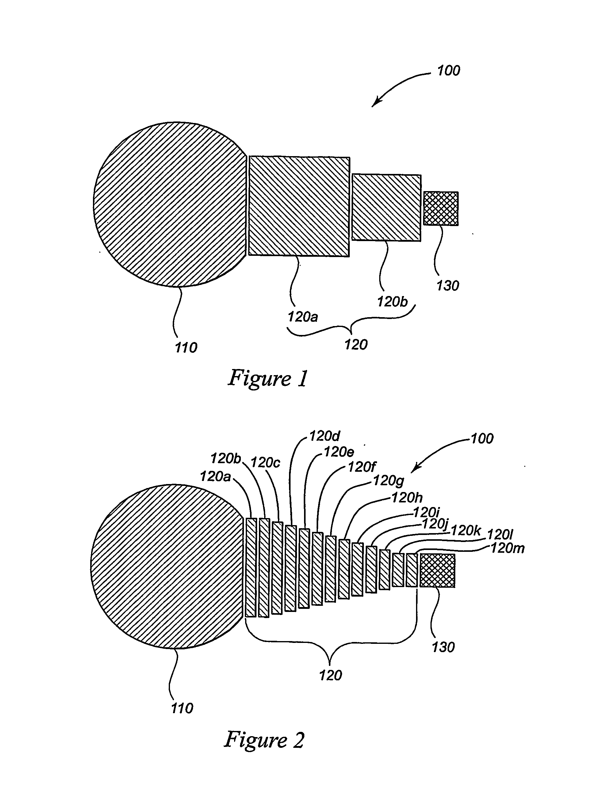
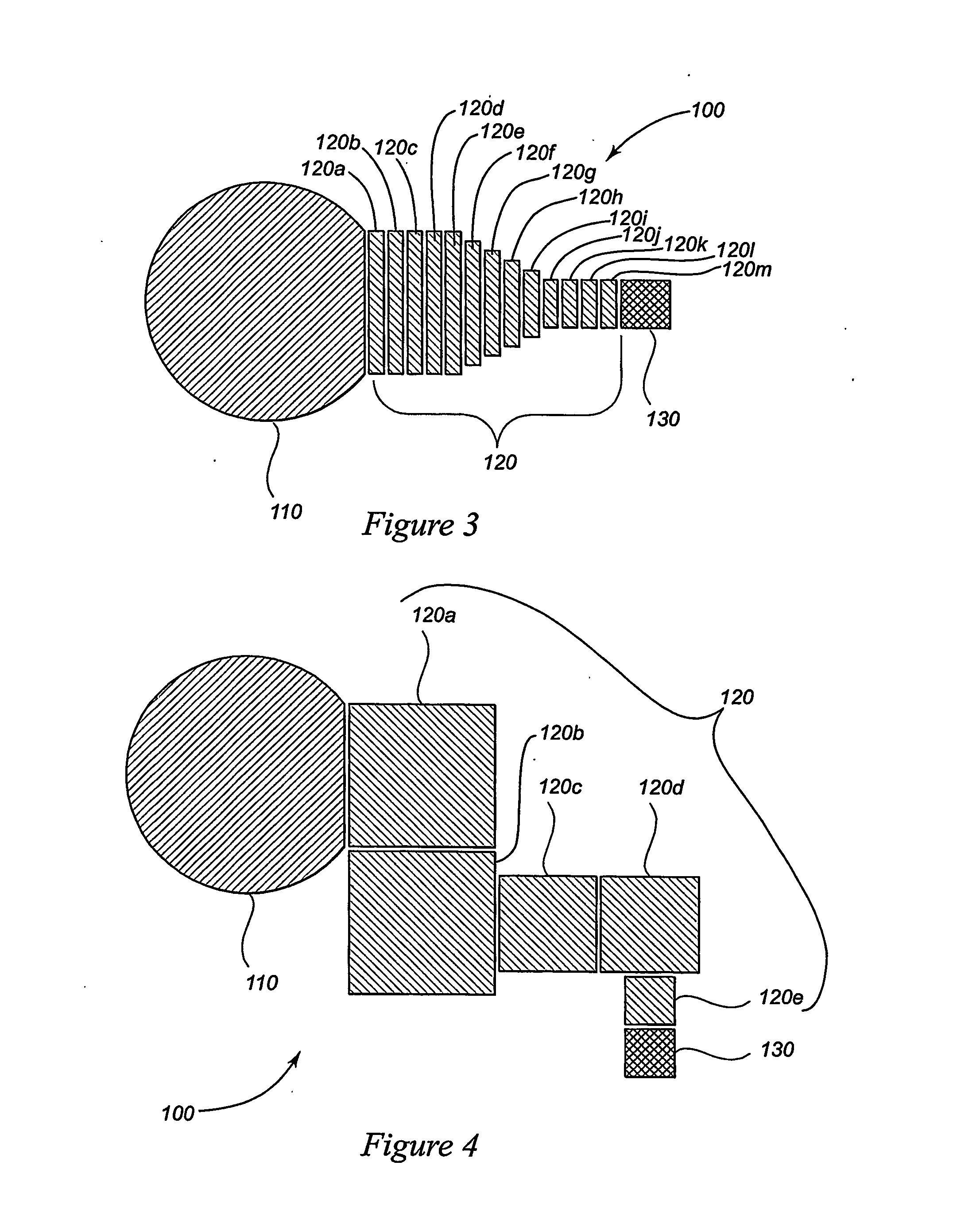
Electro-wettable sample presentation devices are useful in performing analytical measurements such as the detection of analytes contained within a liquid sample drop. The device comprises a virtual microwell for receiving a liquid sample drop; one or more intermediary electro-wettable sites at least one of which is contiguous to the microwell; and a terminal electro-wettable site which confines the deposition of analytes and matrix to within a predetermined area. The microwell is either an electro-wettable zone or a chemically-modified zone which exhibits either hydrophobic and non-adsorptive properties with respect to analytes, or hydrophobic and adsorptive properties with respect to analytes. Each of the electro-wettable sites modifies the surface of the sample presentation device between hydrophobic and hydrophilic states in response to an electrical potential applied between a liquid sample drop and the electro-wettable site so as to direct the positioning of the liquid sample drop.

Description

TECHNICAL FIELD[0001]The present invention relates to the field of matrix-assisted laser desorption / ionization time-of-flight mass spectrometry (MALDI-TOF-MS). More particularly, the present invention relates to sample preparation devices and methods for use in matrix-assisted laser desorption / ionization mass spectrometry with improved analytical detection capabilities.BACKGROUND OF THE INVENTION[0002]Matrix-assisted laser desorption / ionization time-of-flight mass spectrometry is an important analytical tool in proteomics efforts, in that they are dependent upon the ability to rapidly analyze minute quantities of peptide and protein mixtures. Large scale proteomics applications require high sensitivity detection and high sample throughput at moderate cost. These demands underscore the importance of sample preparation and automated data acquisition. In MALDI-TOF-MS, analytes are mixed with a matrix solution in an appropriate solvent and deposited on the surface of a sample support (a...

Claims


Application Information

Patent Timeline
IPC IPC(8): G01N21/01B01L3/00G01N1/00G02BH01J49/16
CPCB01L3/502792B01L3/5088B01L2200/0642B01L2200/0678B01L2300/0829H01J49/0418B01L2300/089B01L2300/161B01L2400/0427G01N1/22B01L2300/087
Inventor STOLOWITZ, MARK L.
Owner STRATOS BIOSYST
Learn More