
Fire Resistant Composite Panel

a composite panel and high strength technology, applied in the direction of thin material processing, construction, layered products, etc., can solve the problems of little additional structural benefit for the structural benefit of the strength to density ratio of about 10000 psi/(g/cc), and achieve the effect of high strength to density ratio, high resistance to combustion or charring, and light weigh

Inactive Publication Date: 2011-04-21
GRAFTECH INT HLDG INC
View PDF22 Cites 37 Cited by
  • Summary
  • Abstract
  • Description
  • Claims
  • Application Information

AI Technical Summary

Benefits of technology

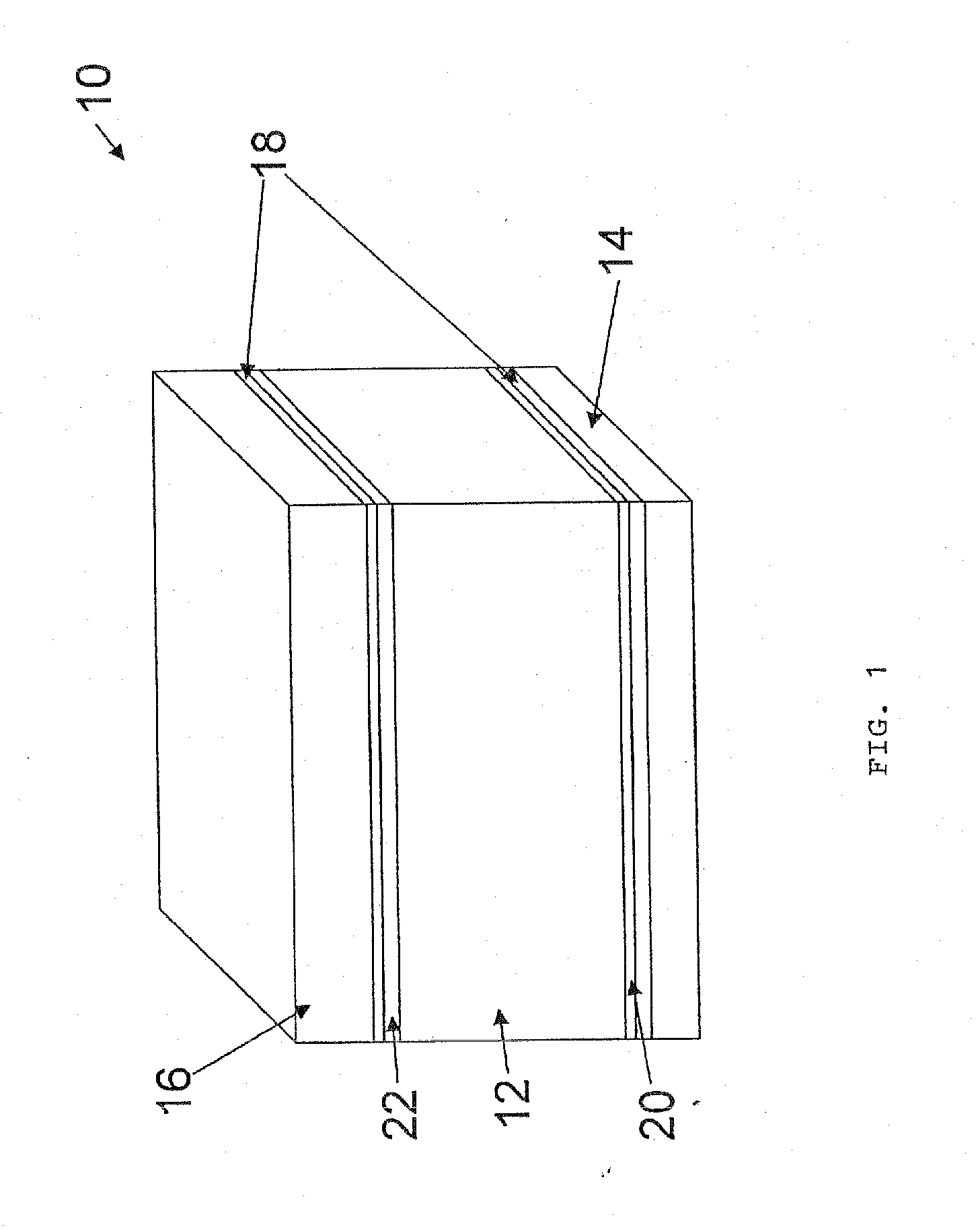
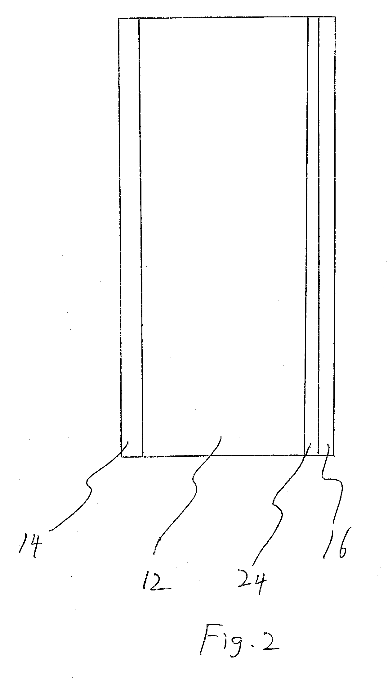
"The present invention provides a composite panel that combines high strength, high resistance to combustion and charring, and EMI shielding. The panel has a unique carbon foam core with a high compressive strength and a density of 0.02 to 0.6 grams per cubic centimeter. The carbon foam core has a uniform density and a minimum strength to density ratio of at least 300 to 10,000 psi. The panel also has a heat spreading layer that rapidly conducts heat from a localized source, and can be coated with various materials to improve its performance. The carbon foam core can be machined or joined with other similar carbon foam sheets to provide larger structural carbon foam panels. The composite panel has good thermal insulation properties and can be produced in a desired size and configuration."

Problems solved by technology

A minimum strength to density ratio is needed to allow for sufficient handling, fabrication, and laminating of the foam in the panel, but strength to density ratios higher than about 10000 psi / (g / cc) provide little additional structural benefit.

Method used


Image

  • Fire Resistant Composite Panel
  • Fire Resistant Composite Panel
  • Fire Resistant Composite Panel

Examples


example i

[0090]Structural insulating panels prepared as described in Table I are prepared. Data is obtained for each panel using an air / propane torch, with the flame tip maintained approximately 3 inches from the panel surface. The time for the torch to burn completely through the construction is measured and set out in Table I.

TABLE IBurn through time (minutes) for variouscarbon foam densitiesDescription0.032 g / cc0.080 g / cc0.16 g / cc1-inch thick foam1327272-inch thick foam35not measurednot measured1-inch thick foam>60>60not measuredwith single heatspreader layer1-inch foam on>60>60not measuredboth sides of headspreader layer

[0091]The results shown in Table I show the improvement in fire resistance when a heat spreading layer is used in conjunction with a carbon foam core. Whereas 1-inch thick samples of foam of any density burn through relatively quickly, even the lowest density foam survives for greater than one hour when it is combined with the inventive heat spreading layer.

example ii

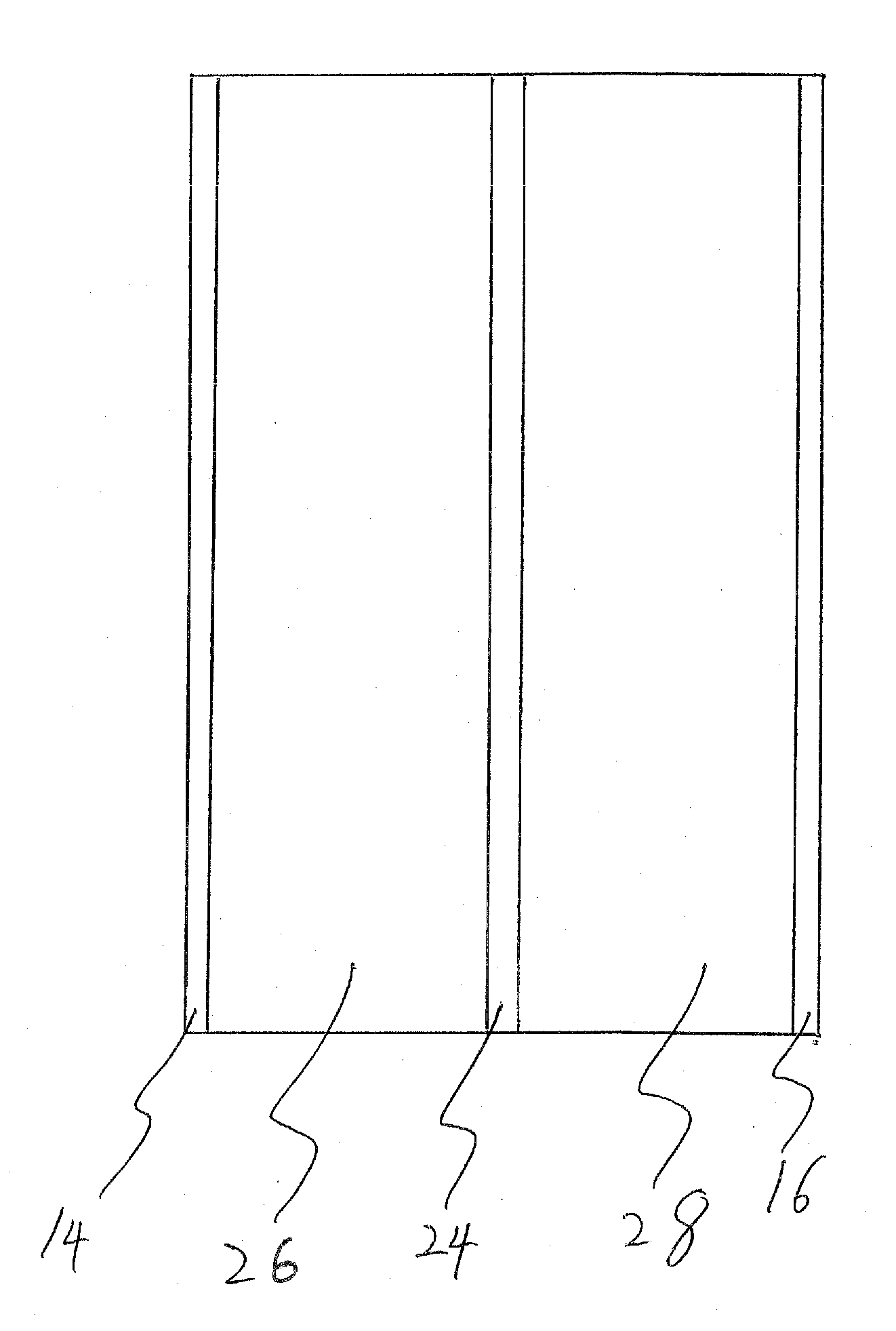
[0092]In a large scale fire test carried out using heat spreader 24 on either side of a 3.5-inch carbon foam core 12 combined with an outer layer 16 of type X gypsum board, the panel achieves an ASTM E-119 fire rating of at least about 2 hours.

[0093]The incorporation of heat spreading layers, especially heat spreading layers of compressed particles of exfoliated graphite, produces a composite panel having improved fire resistance. The anisotropic thermal properties of the compressed exfoliated graphite sheet provide a uniquely adapted heat spreading layer. The very temperature stable carbon foam used in conjunction with the heat spreading layer provides a panel with exceptional fire retardant capabilities. The fire retardancy combined with the strength of the inventive panel provides a significantly improved product for a wide variety of uses.

[0094]Accordingly, by the practice of the present invention, composite panels with carbon foam cores and heat spreading layers, having heretof...


PUM

PropertyMeasurementUnit
thicknessaaaaaaaaaa
thicknessaaaaaaaaaa
thicknessaaaaaaaaaa

Abstract

A composite panel, which includes a heat spreading layer and a carbon foam core having desirable fire retardant properties, and resistance to environmental stress. The composite panel can also include a first layer and a second layer bound to a first surface and second surface of the carbon foam core. Applications of the panel include structural and fire retardant elements of residential and commercial buildings, aircraft and watercraft.

Description

[0001]This application is a continuation in part of U.S. patent application Ser. No. 11 / 314,975, filed Dec. 21, 2005, entitled CARBON FOAM STRUCTURAL INSULATED PANEL, the details of which are incorporated herein by reference.BACKGROUND OF THE INVENTION[0002]1. Technical Field[0003]The present invention relates to high strength, fire resistant composite panels useful for applications including the construction of roofs, floors, walls, doors, elevator shafts, columns, and other structures where a high strength-to-density ratio and improved fire resistance characteristics are useful. Moreover, the inventive composite panels exhibit improved shielding from electromagnetic interference (EMI), making them especially useful in environments where electronics need to be shielded from the effects of electromagnetic interference. More particularly, the present invention relates to the use of carbon foam with an insulating R value of about 3 per inch (meaning that, for every inch in thickness, ...

Claims


Application Information

Patent Timeline
Patent Type & Authority Applications(United States)
IPC IPC(8): C09K21/02B32B5/18
CPCE04B1/942B32B5/18Y10T428/249967B32B3/26B32B9/00
Inventor MILLER, DOUGLAS J.SEGGER, MARKGRIFFIN, YEVGENIY PAVLOVICH
Owner GRAFTECH INT HLDG INC
Learn More