
3D non-volatile memory device and method for operating and fabricating the same

a memory device and non-volatile technology, applied in the field of semiconductor devices, can solve the problems of complex fabrication process, memory device performance degradation, and low manufacturing efficiency, and achieve the effect of improving performance and simplifying the manufacturing process

Active Publication Date: 2011-04-21
SK HYNIX INC
View PDF5 Cites 52 Cited by
  • Summary
  • Abstract
  • Description
  • Claims
  • Application Information

AI Technical Summary

Benefits of technology

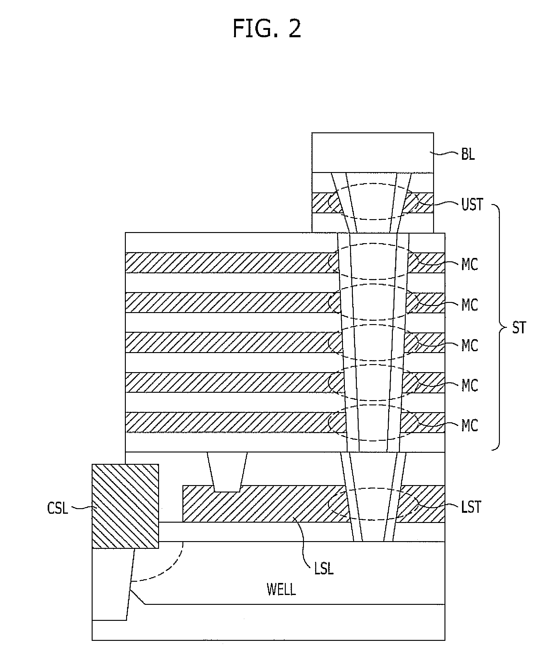
[0023]Exemplary embodiments of the present invention are directed to a 3D non-volatile memory device which is capable of simplifying a fabricating process and improving performance, and methods for operating and fabricating the same.

Problems solved by technology

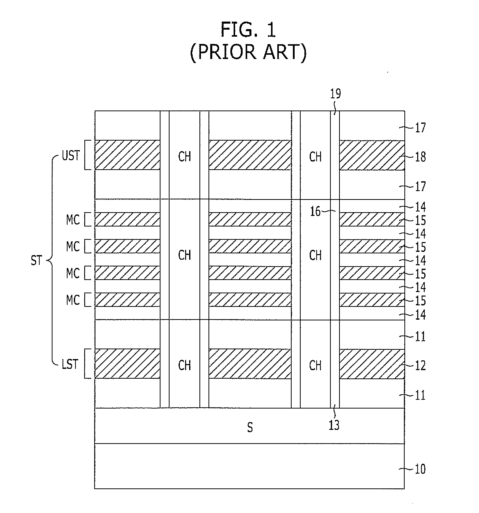
In accordance with the conventional 3D non-volatile memory device described above, the process of fabricating the memory device is relatively complex, and the performance of the memory device may be degraded.
Therefore, the fabricating process thereof is complex, and the manufacturing cost is relatively high.
Second, since the channels of the select transistors LST and UST are formed of amorphous silicon or polycrystalline silicon, on / off characteristics of the select transistors LST and UST may be degraded, and it may be difficult to control the threshold voltage of the transistors.
Therefore, it is highly likely that an error occurs due to the resistance component of the source area S during a read operation.
Fourth, the speed of transferring an erase voltage may be relatively low.
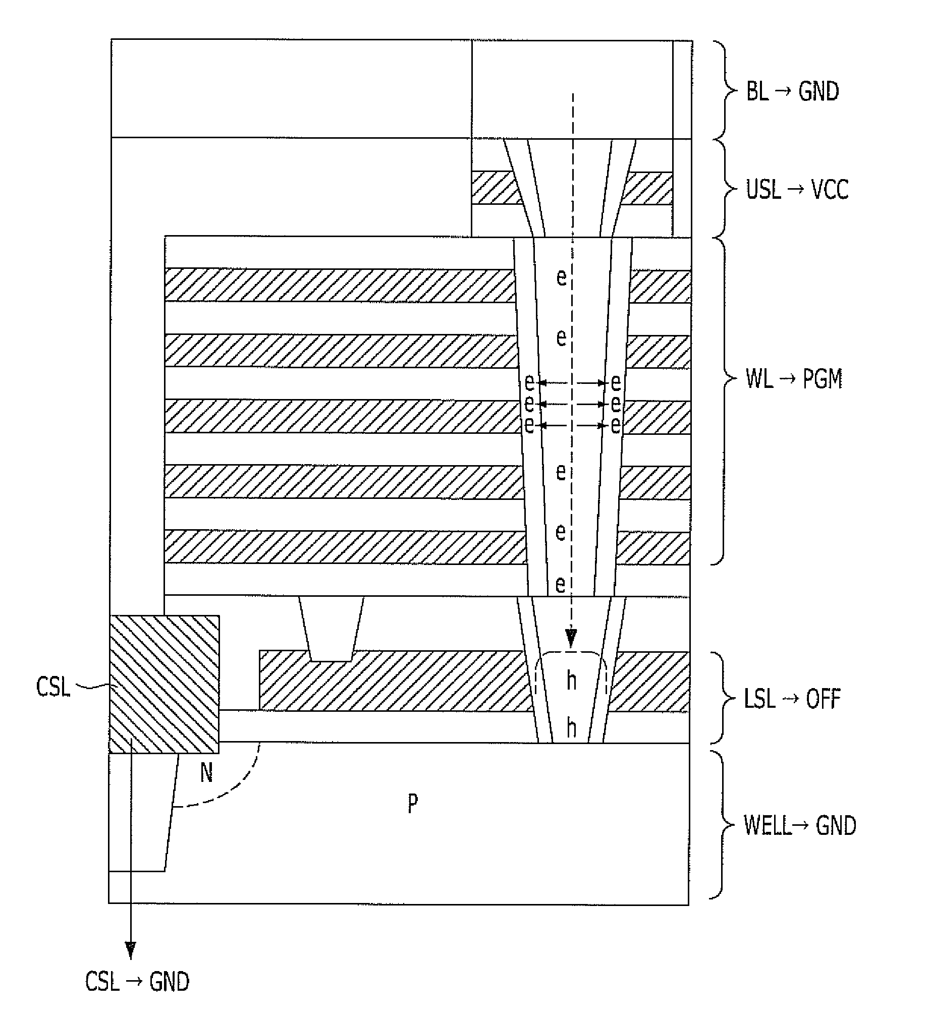
Therefore, when a positive erase voltage is applied to a bit line and the source area S to perform the erase operation, depletion phenomenon may occur.
However, when the high-level erase voltage is applied to ramp the bit line, the upper select transistor UST, and the lower select transistor LST, the threshold voltages of the upper and lower select transistors UST and LST are varied, and the channels CH are damaged.
Furthermore, although the GIDL current is forcibly caused to supply the holes, it is difficult to uniformly distribute the generated holes to the channels CH of the plurality of memory cells MC.
Furthermore, since the bit line, the source area S, the upper select transistor UST, and the lower select transistor LST are all ramped, the power consumption of the semiconductor chip may increase.

Method used


Image

  • 3D non-volatile memory device and method for operating and fabricating the same
  • 3D non-volatile memory device and method for operating and fabricating the same
  • 3D non-volatile memory device and method for operating and fabricating the same

Examples


Embodiment Construction

[0036]Exemplary embodiments of the present invention will be described below in more detail with reference to the accompanying drawings. The present invention may, however, be embodied in different forms and should not be construed as limited to the embodiments set forth herein. Rather, these embodiments are provided so that this disclosure will be thorough and complete, and will fully convey the scope of the present invention to those skilled in the art. Throughout the disclosure, like reference numerals refer to like parts throughout the various figures and embodiments of the present invention.

[0037]The drawings are not necessarily to scale and in some instances, proportions may have been exaggerated in order to clearly illustrate features of the embodiments. When a first layer is referred to as being “on” a second layer or “on” a substrate, it not only refers to a case where the first layer is formed directly on the second layer or the substrate but also a case where a third laye...


PUM


Abstract

A 3D non-volatile memory device includes a plate-type lower select line formed over a substrate, a lower select transistor formed in the lower select line, a plurality of memory cells stacked over the lower select transistor, an upper select transistor formed over the memory cells, and a line-type common source line formed over the substrate and spaced from the lower select line.

Description

CROSS-REFERENCE TO RELATED APPLICATIONS[0001]The present application claims priority of Korean Patent Application No. 10-2009-0099233, filed on Oct. 19, 2009, which is incorporated herein by reference in its entirety.BACKGROUND OF THE INVENTION[0002]Exemplary embodiments of the present invention relate to a semiconductor device and a method for fabricating the same, and more particularly, to a 3D non-volatile memory device and a method for fabricating the same.[0003]A non-volatile memory device is a memory device which is capable of maintaining data stored therein, even though power supply is cut off. As a 2D memory device in which memory cells are formed as a single layer on a silicon substrate is reaching its limits in achieving high integration, a 3D non-volatile memory device is being developed, in which memory cells are vertically stacked on a silicon substrate.[0004]Hereafter, the structure of a conventional 3D non-volatile memory device and the concern therein are described w...

Claims


Application Information

Patent Timeline
IPC IPC(8): G11C16/04H01L29/772H01L21/336
CPCG11C16/0483G11C16/10H01L27/11526G11C16/26H01L27/11556H01L27/11573H01L27/11578H01L27/11551H10B41/40H10B41/20H10B41/27H10B43/40H10B43/20H01L27/0688
Inventor YOO, HYUN-SEUNGCHOI, EUN-SEOKKIM, SE-JUN
Owner SK HYNIX INC
Learn More