
Image processing apparatus and method controlling the amount of transparent ink for recording

a technology of transparent ink and image processing, which is applied in the field of image processing apparatus and image processing method, and the field of computer programs, can solve the problems of increasing the amount of calculation, and being able to perform the same process. the effect of reducing the productivity of the apparatus

Inactive Publication Date: 2011-04-21
CANON KK
View PDF8 Cites 10 Cited by
  • Summary
  • Abstract
  • Description
  • Claims
  • Application Information

AI Technical Summary

Benefits of technology

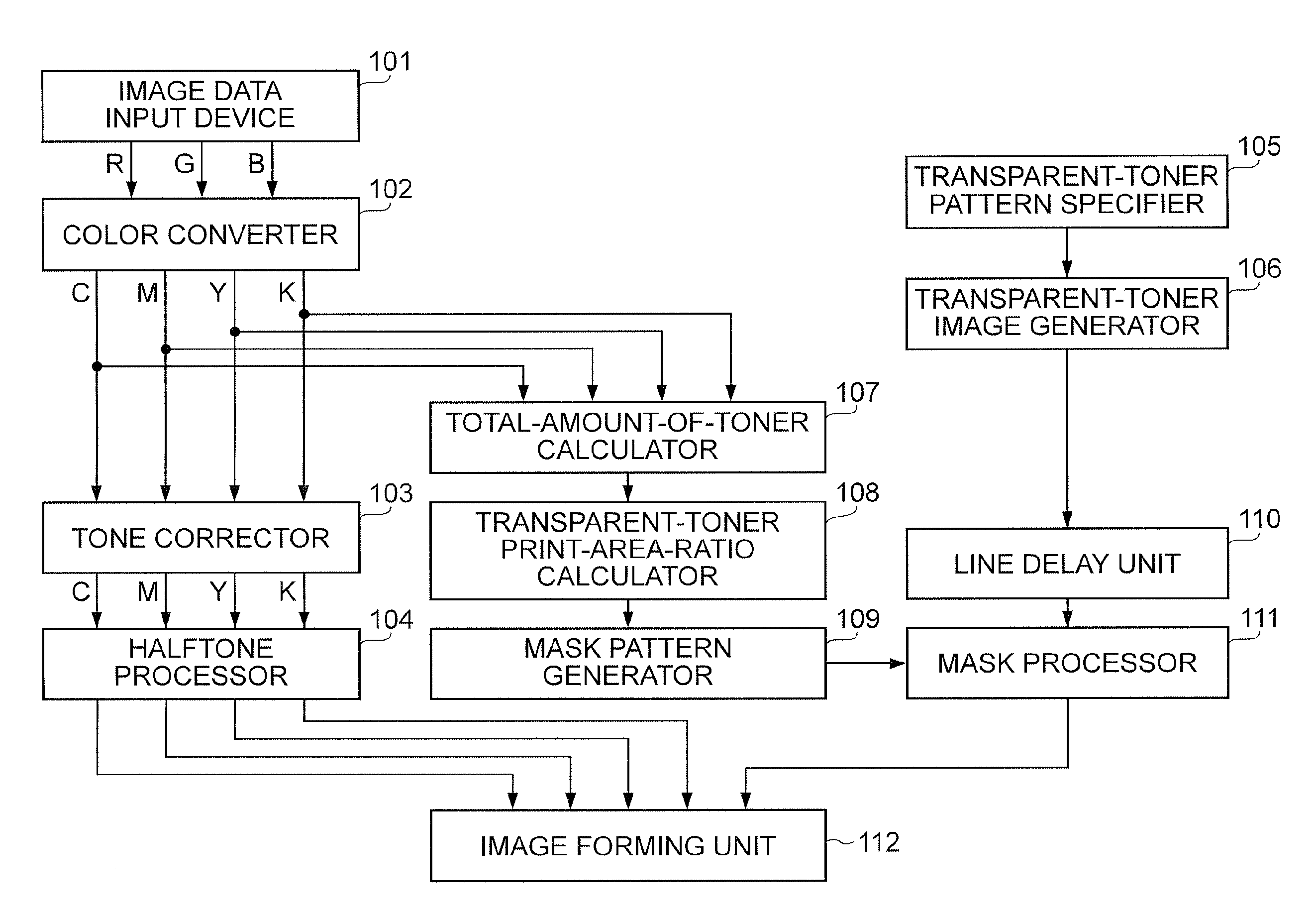
The present invention provides an image processing apparatus that can control the amount of toner per unit area when printing with special toner without reducing productivity. The apparatus includes a calculation unit to calculate the amount of a first coloring material in an area, a determination unit to determine an allowable amount of a second coloring material in the area based on the amount of the first coloring material and a limit of the second coloring material, and a control unit to control the amount of the second coloring material in the area so as not to exceed the allowable amount. This allows for efficient use of coloring materials and improved image quality.

Problems solved by technology

However, with this structure, it is necessary to perform the same series of processes multiple times, and thus the productivity of the apparatus is reduced.
However, since the special toner cannot be replaced with another toner component, it is not possible to perform the same process when the special toner, such as the transparent toner, is added.
In addition, although the amount of toner is conventionally controlled for every pixel, applying the same process to the printing of additional image information with the toner having a special function, such as the transparent toner, not only increases the amount of calculation but also makes the relative amount of the transparent toner for every pixel unstable to possibly decrease the stability of the additional information.
However, the control of the amount of toner per unit area is not performed in this technology.

Method used


Image

  • Image processing apparatus and method controlling the amount of transparent ink for recording
  • Image processing apparatus and method controlling the amount of transparent ink for recording
  • Image processing apparatus and method controlling the amount of transparent ink for recording

Examples


first exemplary embodiment

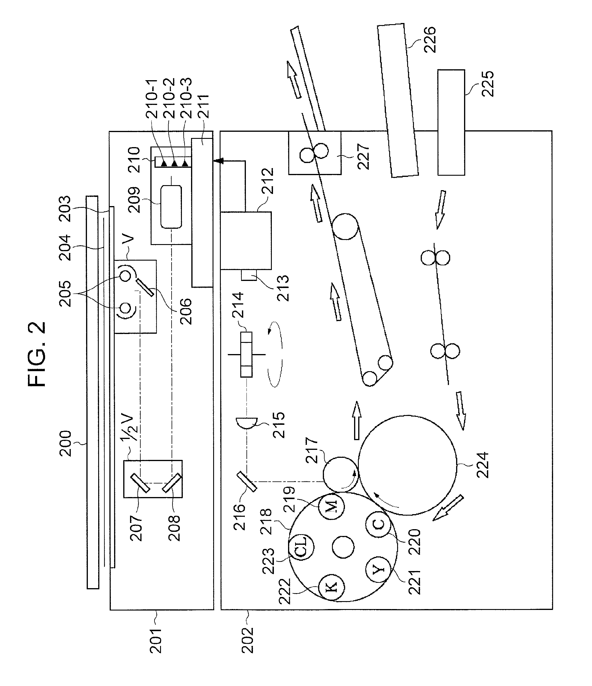
[0030]FIG. 10 is a block diagram schematically showing an example of the structure of an image forming apparatus 1000 according to a first exemplary embodiment of the present invention. A common digital multifunction machine having copy, print, facsimile and other functions is used as the image forming apparatus 1000 in the first exemplary embodiment. Referring to FIG. 10, the image forming apparatus 1000 includes a scanner unit 1001 that scans the document and a controller unit 1002 that performs image processing for the image data scanned by the scanner unit 1001 and stores the processed image data in a memory 1005. The image forming apparatus 1000 also includes an operational unit 1004 that sets various print setup conditions for the image data scanned by the scanner unit 1001. The image forming apparatus 1000 further includes a printer unit 1003 that forms a visual image of the image data read out from the memory 1005 on a recording sheet of paper in accordance with the print se...

second exemplary embodiment

[0078]A second exemplary embodiment of the present invention will be described. The same reference numerals are used in the second exemplary embodiment to identify appropriately the same components shown in the first exemplary embodiment. A detailed description of such components is omitted herein.

[0079]The transparent toner is superimposed on the document that is scanned by the scanner and is copied in the first exemplary embodiment. In contrast, according to the second exemplary embodiment, the transparent toner is superimposed on an electronic document that is printed from an information processing apparatus, such as a PC, via a printer driver.

[0080]A bitmap image supplied from a raster image processor (RIP), which expands electronic information described in a page description language etc. into a raster image, is input into the image data input device 101 in FIG. 1.

[0081]The transparent toner pattern may be input and set on an operation screen of the printer driver in the comput...

third exemplary embodiment

[0083]A third exemplary embodiment of the present invention will be described. The same reference numerals are used in the third exemplary embodiment to identify appropriately the same components shown in the first exemplary embodiment. A detailed description of such components is omitted herein.

[0084]The total amount of toner is calculated before the halftone processing in the first and second exemplary embodiments. In contrast, according to the third exemplary embodiment, the total amount of toner is calculated after the halftone processing.

[0085]FIG. 7 is a block diagram showing in detail an example of the structure of a controller unit 1002 according to the third exemplary embodiment. The controller unit 1002 in the third exemplary embodiment differs from the controller unit 1002 in the first exemplary embodiment only in a total-amount-of-toner calculator 107-2. Other components in the controller unit 1002 in the third exemplary embodiment are the same as the controller unit 100...


PUM


Abstract

An image processing apparatus includes a calculation unit configured to calculate an amount of a first coloring material in an area including a plurality of pixels; a determination unit configured to determine an allowable amount of a second coloring material in the area on the basis of the amount of the first coloring material, calculated by the calculation unit, and a limit of the amount of the coloring material; and a control unit configured to control an amount of the second coloring material in the area so as not to exceed the allowable amount of the second coloring material.

Description

TECHNICAL FIELD[0001]The present invention relates to an image processing apparatus, an image processing method, and a computer program, which control the amount of a color material used for recording.BACKGROUND ART[0002]Digital printing technologies have been increasing the utility value in on-demand printing markets and printing markets requiring a small number of documents in recent years. In particular, full-color printing using an electrophotographic technology holds superiority in the productivity, printing cost, ease of maintenance, etc. over other printing technologies and has been rapidly expanding its market.[0003]Both full-color printing using toner of four colors (cyan, magenta, yellow, and black (CMYK)) by the electrophotographic technology, and multicolor printing using special toner, are receiving attention and come within the range of special printing markets requiring a higher level of on-demand features and immediacy.[0004]Multicolor printing using special toner is...

Claims


Application Information

Patent Timeline
Patent Type & Authority Applications(United States)
IPC IPC(8): H04N1/60
CPCH04N1/60H04N1/52
Inventor OHTA, KEN-ICHIOTAKE, RITSUKO
Owner CANON KK
Learn More