
Imaging device, imaging method, and electronic apparatus

a technology of imaging device and electronic apparatus, applied in the direction of color signal processing circuit, color television details, television system, etc., can solve the problem of distorted linearity of picked-up image signal after combination

Active Publication Date: 2011-04-21
ADVANCED INTERCONNECT SYST LTD
View PDF12 Cites 20 Cited by
  • Summary
  • Abstract
  • Description
  • Claims
  • Application Information

AI Technical Summary

Benefits of technology

[0016]When the ratios of the exposures are equalized, light responses (output pixel signal levels) of the imaging unit with respect to an incident light amount (a logarithm) can be arranged at equal intervals. Consequently, since an exposure ratio of images to be combined is always fixed, a change in brightness over a dark section to a bright section is equal. There is an effect that an image with little occurrence of noise can be obtained.
[0020]Consequently, an exposure ratio of images to be combined is always fixed and, in an image after combination, a change in brightness over a dark section to a bright section is equal. There is an effect that an image with little occurrence of noise can be obtained.
[0031]With such a configuration, by setting desired minimum and maximum, it is possible to easily calculate, according to Formula (1), an intermediate exposure of exposures, the ratios of the respective pairs of exposures adjacent to each of which in an ascending order or a descending order are equal.
[0034]Consequently, it is possible to adjust, according to a bright environment, a dark environment, or the like, an exposure to an exposure suitable for the brightness of the imaging environment while keeping the ratios equal. Therefore, a change in brightness over a dark section to a bright section is equal. There is an effect that it is possible to set an exposure more suitable for the imaging environment while maintaining an effect that an image with little occurrence of noise can be obtained.

Problems solved by technology

In such a case, it is likely that the coefficient values “T3 / T1” and “T3 / T2” are inappropriate and the linearity of a picked-up image signal after combination is distorted.

Method used


Image

  • Imaging device, imaging method, and electronic apparatus
  • Imaging device, imaging method, and electronic apparatus
  • Imaging device, imaging method, and electronic apparatus

Examples


first embodiment

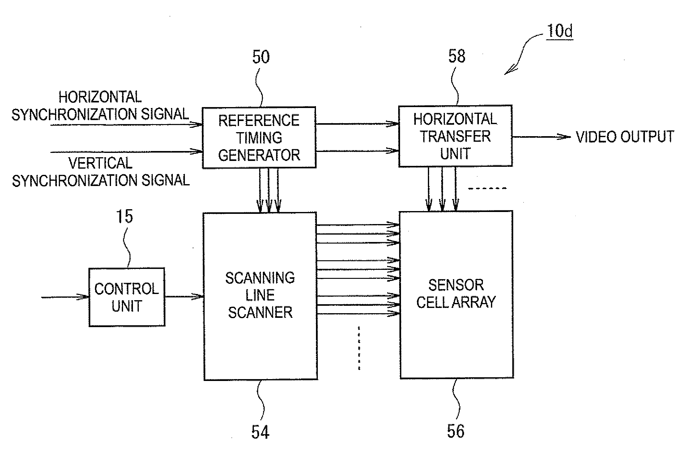
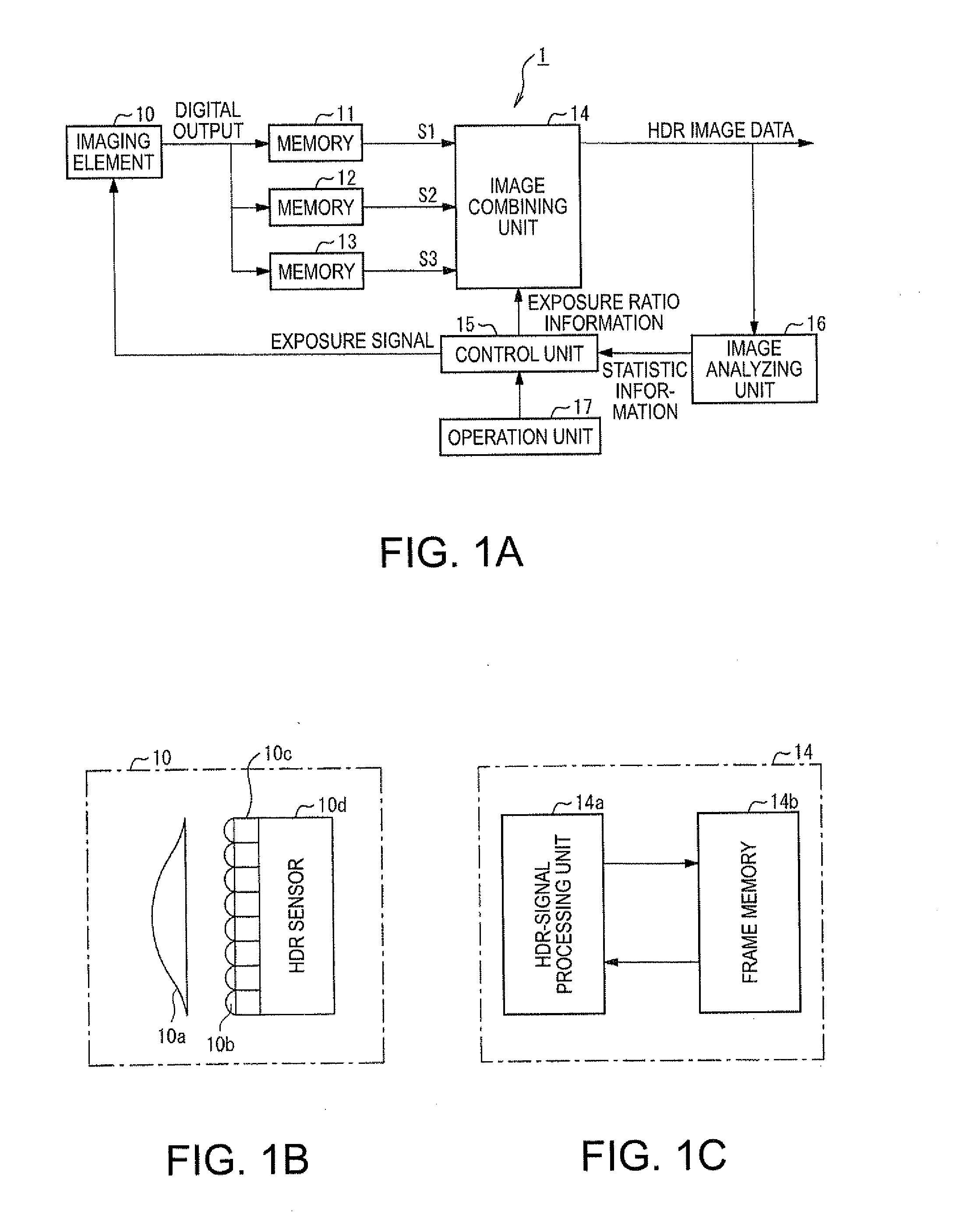
[0053]A first embodiment of the invention is explained below with reference to the accompanying drawings. FIGS. 1A to 1C to FIG. 9 are diagrams showing the first embodiment of an imaging device, an imaging method, and an electronic apparatus according to the invention.

[0054]First, the configuration of the imaging device according to the invention is explained with reference to FIGS. 1A to 1C. FIG. 1A is a block diagram showing the configuration of an imaging device 1 according to the invention. FIG. 1B is a schematic diagram showing the configuration of an imaging element 10. FIG. 1C is a block diagram showing the configuration of an image combining unit 14.

[0055]The imaging device 1 includes, as shown in FIG. 1A, the imaging element 10, memories 11 to 13, the image combining unit 14, a control unit 15, an image analyzing unit 16, and an operation unit 17.

[0056]The imaging element 10 has a function of imaging a subject with three or more kinds of exposures. The imaging element 10 in...

second embodiment

[0171]A second embodiment of the invention is explained below with reference to the accompanying drawings. FIG. 10 is a diagram showing the second embodiment of the imaging device, the imaging method, and the electronic apparatus according to the second embodiment of the invention.

[0172]This embodiment is different from the first embodiment in that the control unit 15 of the imaging element 10 according to the first embodiment selects, according to a selection instruction from a user via the operation unit 17, any one determination method out of plural kinds of determination methods (modes) for exposure ratio information and determines an exposure ratio (generates exposure ratio information) in the selected determination mode. This embodiment is also different from the first embodiment in that a calculated ratio of exposure times is adjusted such that all of the shortest exposure time T1, the intermediate exposure time T2, and the longest exposure time T3 are natural numbers.

[0173]T...


PUM


Abstract

An imaging device includes: an imaging unit that images a subject with three or more kinds of exposures, ratios of respective pairs of exposures of which adjacent to each other in an ascending order or a descending order are equal; and a combining unit that combines, on the basis of the ratios, pixel signals corresponding to the respective three or more kinds of exposures obtained by imaging the subject with the imaging unit.

Description

[0001]This application claims priority based on Japanese Patent Application No. 2009-242817, filed on Oct. 21, 2009, which is incorporated in this specification.BACKGROUND[0002]1. Technical Field[0003]An aspect of the present invention relates to an imaging device, an imaging method, an electronic apparatus, and the like suitable for combining plural kinds of picked-up image data having different exposures and generating image data having an expanded dynamic range.[0004]2. Related Art[0005]In the related art, there is a technique for imaging the same subject with plural kinds of exposures (exposure times), combining pixel signals obtained by the imaging respectively corresponding to the plural kinds of exposures, and generating image data having an expanded dynamic range (HDR image data). In such a technique, noise (a false color, a pseudo contour, etc.) often occurs in a boundary area between an image portion corresponding to each of the exposures and image portions corresponding t...

Claims


Application Information

Patent Timeline
Patent Type & Authority Applications(United States)
IPC IPC(8): H04N5/228H04N23/40H04N25/00
CPCH04N5/35581H04N5/35554H04N25/583H04N25/589
Inventor KOBAYASHI, MASANOBUKURANE, HARUHISA
Owner ADVANCED INTERCONNECT SYST LTD
Learn More