
Brake auxiliary system of electric car

a technology of auxiliary system and brake, which is applied in the direction of brake system, vehicle components, transportation and packaging, etc., can solve the problems of ineffective auxiliary system of brake, high possibility of failure, and high energy consumption of brakes, so as to prolong the life of brakes, reduce failure rate, and maintain stable vacuum inside the vacuum container

Inactive Publication Date: 2011-04-21
FENG SEN +2
View PDF4 Cites 13 Cited by
  • Summary
  • Abstract
  • Description
  • Claims
  • Application Information

AI Technical Summary

Benefits of technology

[0004]To conquer the above-mentioned disvantages, the present invention provides a brake auxiliary system having a vacuum container, the system can attain a stable vacuum when the vacuum pump work intermittently, and it is green and energy-saving.
[0007]Firstly, by introducing the vacuum container to store a certain vacuum, the vacuum pump is enable to work intermittently, thus the frequent starts of the vacuum pump when brake can be avoided and the life of the brake can be extended, and the failure rate can be reduced too.
[0008]Secondly, because of the pressure detector and the delay control switch, the vacuum inside the vacuum container is kept stable, and the efficiency of vacuum booster is ensured, the cost is low, and the structure is simple and reliable.
[0009]Thirdly, it is green and energy-saving, and it can reduce the energy consumption of the electric car auxiliary power supply and further increase the driving miles.

Problems solved by technology

In order to achieve the efficiency of the brake power, a vacuum pump has to work continually to maintain the vacuum, this brings large energy consumption and big noise.
And the ongoing work of the vacuum pump makes the possibility of failure higher, once the vacuum pump fails, the brake auxiliary system will be ineffective without vacuum source, and the consequences is unthinkable.

Method used


Image

  • Brake auxiliary system of electric car
  • Brake auxiliary system of electric car
  • Brake auxiliary system of electric car

Examples


Embodiment Construction

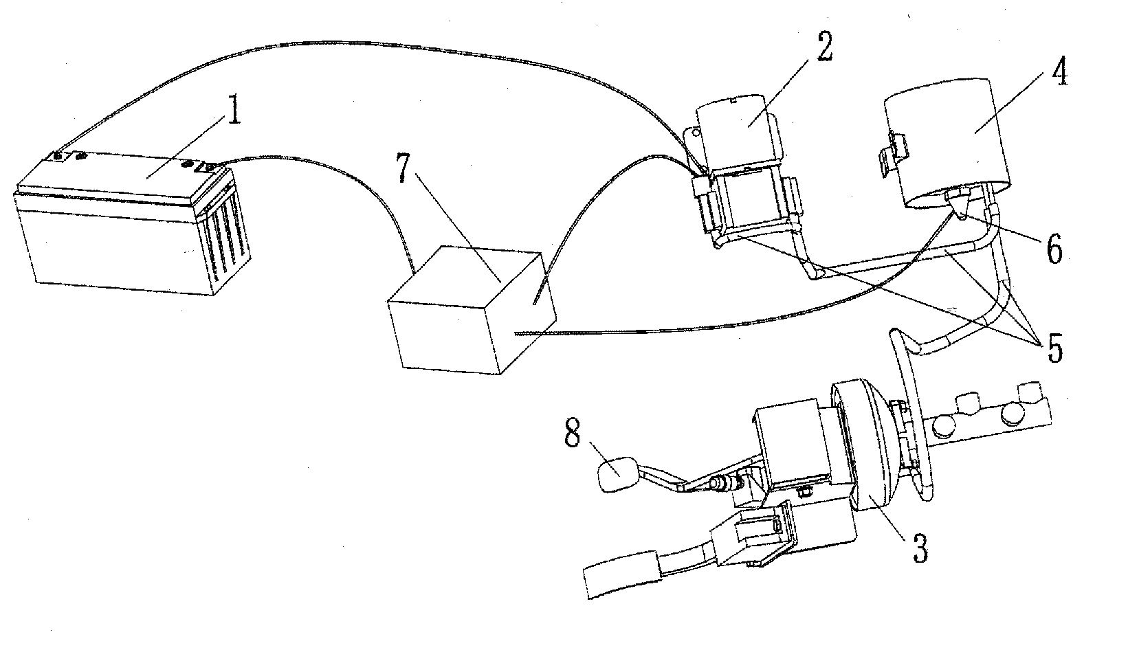
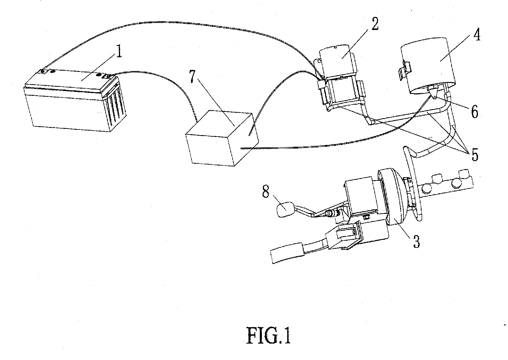
[0012]Referring to FIG. 1, a brake auxiliary system of electric car comprises an auxiliary power supply 1, a vacuum pump 2, a vacuum booster 3, a vacuum pipe 5 and a vacuum container 4, wherein the vacuum booster 3 is connected to the vacuum container 4 through the vacuum pipe 5 and is also connected to the vacuum pump 2 through the vacuum pipe 5, the auxiliary power supply 1 supplies power to the vacuum pump 2.

[0013]A pressure detector 6 and a delay control switch 7 are disposed on the said vacuum container 4, and the delay control switch 7 is electrically connected with the auxiliary power supply 1 The pressure detector 6 is provided for detecting the vacuum pressure in the vacuum container 4, and the delay control switch 7 is provided for controlling the connection of the vacuum pump 2 and the vacuum container 4, when the vacuum pressure in the vacuum container 4 detected by the pressure detector 6 is higher than the set value, the vacuum pump 2 will start to pump vacuum, and whe...


PUM


Abstract

The invention discloses a brake auxiliary system having a vacuum container, which comprises an auxiliary power supply, a vacuum pump, a vacuum booster and a vacuum container, wherein the vacuum container and the vacuum booster are both connected with the vacuum pump which supplied power by the auxiliary power supply, a pressure detector and a delay control switch are disposed on the vacuum container, keeping the vacuum degree in the vacuum container within a certain range. The vacuum container of the present invention makes the vacuum pump enable to work intermittently, avoiding frequent start of the vacuum pump when brake and also extending the life of the brake. Because of the pressure detector and the delay control switch, the vacuum inside the vacuum container is kept stable, and the efficiency of vacuum booster is ensured. The invention has low cost, simple and reliable structure, it is green and energy-saving, and it can reduce the energy consumption of the electric car auxiliary power supply and increase the driving miles.

Description

CROSS-REFERNCE TO RELATED DOCUMENTS[0001]The present invention claims priority from China patent application No 200910209815.X, entitled BRAKE AUXILIARY SYSTEM OF ELECTRIC CAR and filed on Oct. 21, 2009, the entire content of which is incorporated herein by reference.FIELD OF THE INVENTION[0002]The present invention relates to a brake auxiliary system of car, and particularly relates to an electric power brake auxiliary system of electric car.BACKGROUND OF THE INVENTION[0003]At present, a car generally has brake power especially vacuum brake booster, a fuel-engined car ensures its brake power mainly depending on the vacuum degreed of the intake manifold when the engine is on operation However, in an electric car, the brake power is generally ensured by the pumping work of the electric vacuum pump. In order to achieve the efficiency of the brake power, a vacuum pump has to work continually to maintain the vacuum, this brings large energy consumption and big noise. And the ongoing wor...

Claims


Application Information

Patent Timeline
IPC IPC(8): B60T13/52B60T13/46
CPCB60T17/02B60T13/52
Inventor FENG, SENXU, QIANGWU, SENCHANG
Owner FENG SEN
Learn More