
Portable working machine

a working machine and portability technology, applied in the direction of machines/engines, ignition safety means, transportation and packaging, etc., can solve the problem of the gas-engine generator unit that is combined and falls down

Active Publication Date: 2011-04-21
HONDA MOTOR CO LTD
View PDF4 Cites 3 Cited by
  • Summary
  • Abstract
  • Description
  • Claims
  • Application Information

AI Technical Summary

Benefits of technology

[0005]It is accordingly an object of the present invention to provide a portable working machine which is capable of protecting itself from damages caused due to falling of the portable working machine.
[0007]With this arrangement, the horizontal accelerations induced in the portable working machine are detected by the acceleration sensor, and the control unit stops the engine when it determines that a tip angle of the portable working machine which is determined based on the detected horizontal accelerations exceeds a reference angle. The generator will stop as the engine is stopped. The control unit is able to conduct determination as to whether the engine is to be stopped or not before the portable working machine has fallen down. The reference angle may be set to an optimal value in view of the center of gravity, weight, size and other physical properties as well as use conditions of the portable working machine. Thus, when the portable working machine is falling during operation, the engine is stopped properly at right timing, thereby protecting the portable working machine from damage.
[0009]Preferably, the control unit is configured to, when it determines that the tip angle exceeds the reference angle, execute control in such a manner that a rotational speed of the engine is reduced to a preset reference speed. The preset reference speed is an idling speed, for example. This arrangement is particularly advantageous when the portable working machine restores its upright posture after slight tipping. While the portable working machine is in a tipped or inclined state, the engine is running at idling speed. When the upstanding posture of the working portable machine is restored, the engine is brought back to a former running condition. With this arrangement, the portable working machine can continue its operation in a stable manner.

Problems solved by technology

The portable combined gas-engine generator unit is simply placed on the floor without anchoring, and hence, it may occur that the combined gas-engine generator unit falls down due to some reasons depending on installation conditions.

Method used


Image

  • Portable working machine
  • Portable working machine
  • Portable working machine

Examples


Embodiment Construction

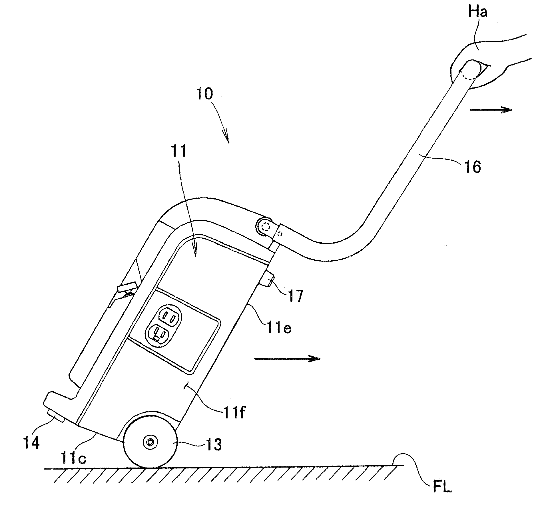
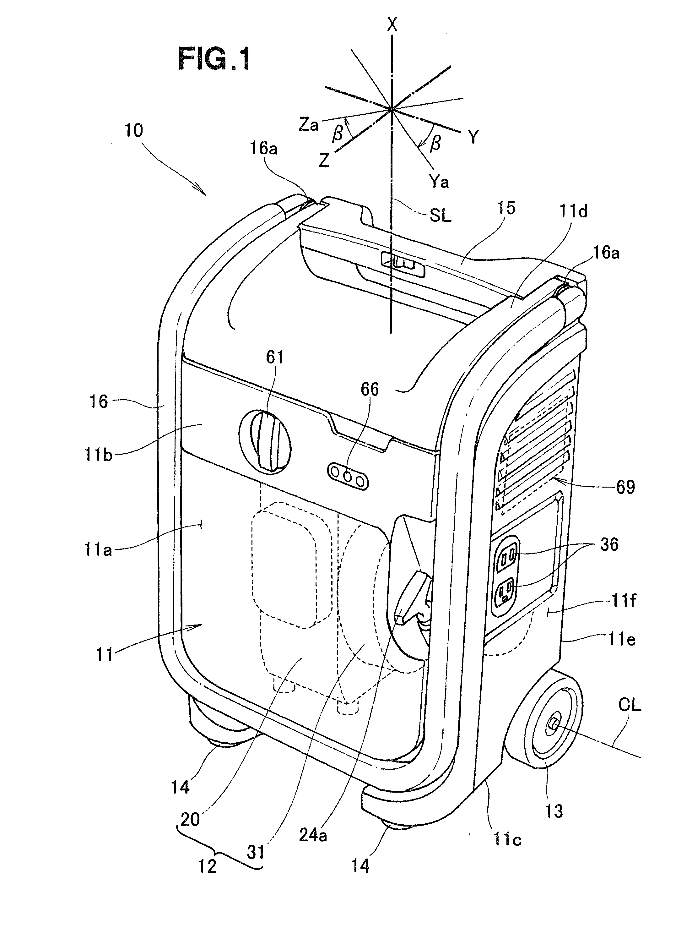
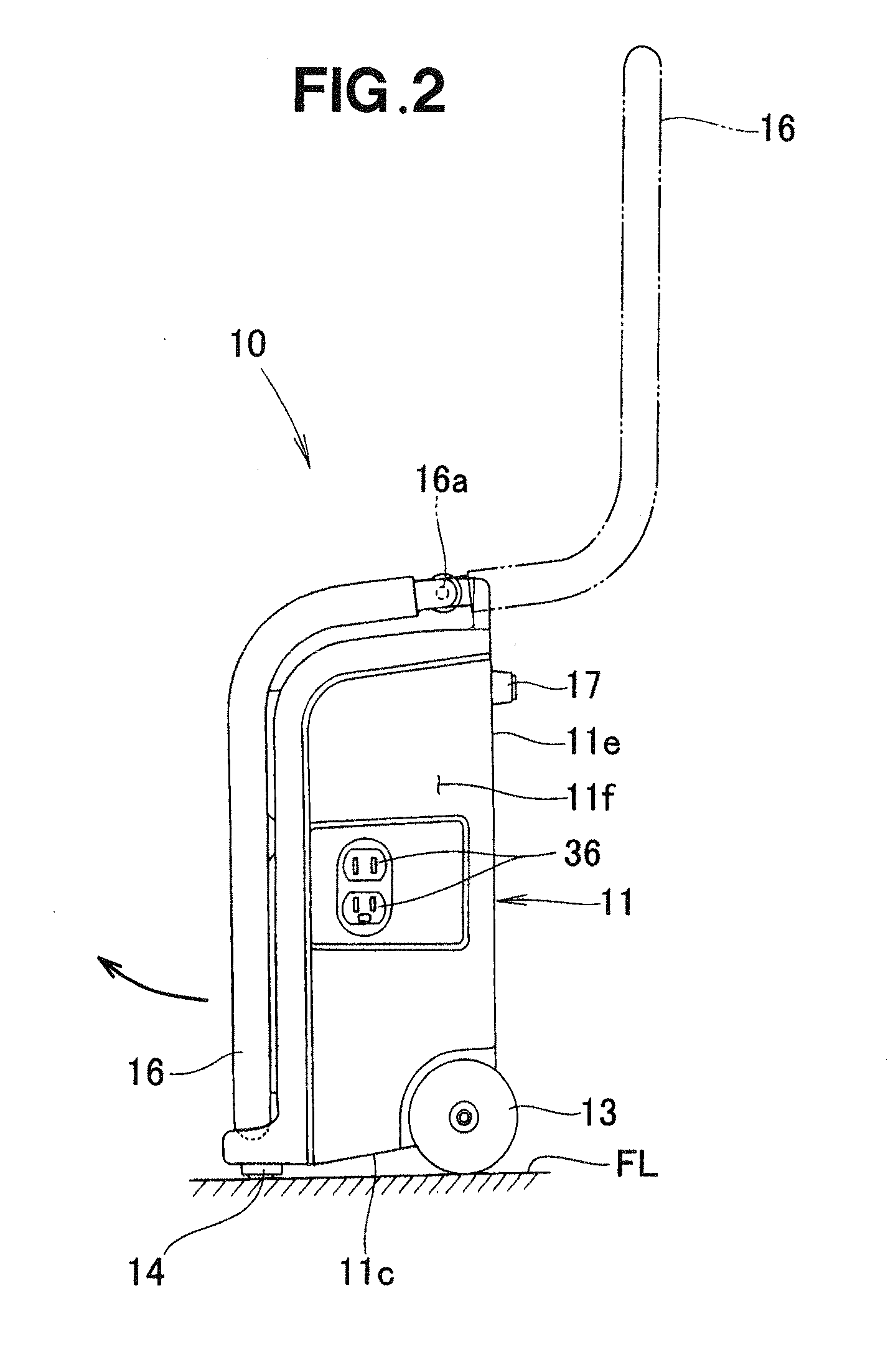
[0024]FIG. 1 shows a gas engine-driven portable generator 10 exemplifying a portable working machine according to the present invention. The portable generator 10 is shown as being in an upright position or posture. The gas engine-driven portable generator 10 is a kind of working machine, which can be carried by a human operator and can freely be transferred to a desired job site.

[0025]As shown in FIG. 1, the portable generator 10 generally includes an elongated, substantially rectangular parallelepiped container or case 11, and a combined engine-generator unit 12 housed in the case 11. The case 11 has a front panel 11a adapted to be located on a front side of the portable generator 10 while the portable generator 10 is in use, and a control section 11b provided on the front panel 11a. Parts of the portable generator 10 are oriented such that a plane including the front panel 11a forms a front face of the portable generator 10. The case 11 is provided with left and right carrier whe...


PUM


Abstract

A portable working machine includes a gaseous-fueled engine, a working unit driven by the engine, a control unit for controlling the engine and the working unit, and an acceleration sensor capable of detecting accelerations in two mutually perpendicular horizontal directions relative to a vertical line, which is induced in the portable working machine. The control unit is configured to determine a tip angle of the portable working machine based on the horizontal accelerations detected by the acceleration sensor and issue a stop instruction to the engine when it determines that the tip angle exceeds a preset reference angle.

Description

FIELD OF THE INVENTION[0001]The present invention relates generally to a portable working machine equipped with a gaseous-fueled engine, and more particularly to a falling detection technology for detecting falling of such portable working machine.BACKGROUND OF THE INVENTION[0002]Working machines include portable working machines that can freely be transferred to a field site, and some kinds of such portable working machines have a working unit driven by a gaseous-fueled engine (hereinafter-referred to, for brevity, as “gas engine”). One example of such working unit is a combined gas-engine generator unit disclosed, for example, in Japanese Patent Laid-Open Publication (JP-A) No. 2006-97584.[0003]The disclosed combined gas-engine generator unit includes a gas engine drivable by a fuel supplied from a gas cartridge, a generator driven by the gas engine, and a controller for controlling the gas engine and the generator. The gas cartridge, the gas engine, the generator and the controll...

Claims


Application Information

Patent Timeline
Patent Type & Authority Applications(United States)
IPC IPC(8): F02P11/00F02B43/00F02B63/00F02B63/04F02D19/02F02M21/02F02M21/06
CPCB62B1/00F02B63/04F02B63/02B62B5/067
Inventor FUKANO, JUN
Owner HONDA MOTOR CO LTD
Learn More