Radio communication system, network side device, small cell base station, and transmission power control method

a communication system and network side technology, applied in power management, transmission monitoring, wireless commuication services, etc., can solve the problems of increasing the interference amount of the small cell terminal the method disclosed in non-patent literature 1 does not take into account the case, and the communication rate of the radio terminal to be connected to the large cell base station is largely decreased. , to achieve the effect of reducing the communication rate of the radio terminal connected

Active Publication Date: 2011-04-14
KYOCERA CORP
View PDF14 Cites 18 Cited by
  • Summary
  • Abstract
  • Description
  • Claims
  • Application Information

AI Technical Summary

Benefits of technology

[0012]Accordingly, an objective of the present invention is to provide a radio communication system, a network side device, a small cell base station, and a transmission power control method with which a decrease of a communication rate of a radio terminal connected to a large cell base station can be suppressed even when the number of small cell base stations within a large cell changes.
[0014]With the aspect, an upper-limit value of an amount of interference which is received by the large cell base station from each of the small cell terminals is determined based on a permissible value of the total amount of interference which is received by the large cell base station from the radio terminals (i.e., a small cell terminal) connected to the small cell base stations and the number of the small cell base stations within the large cell. The small cell base station determines a maximum value of transmission power of the small cell terminal according to the upper-limit value and the propagation loss from the small cell terminal to the large cell base station and controls the transmission power of the small cell terminal so the transmission power does not exceed the determined maximum value.
[0015]Consequently, even when the number of the small cell base stations within the large cell is changed, an amount of interference from the small cell terminal to the large cell base station can be kept equal to or smaller than the permissible value and the decrease of the transmission rate of the radio terminal connected to the large cell base station can be suppressed.
[0023]A ninth aspect of the present invention is a transmission power control method of controlling transmission powers of radio terminals connected to small cell base stations in a radio communication system in which each of the small cell base stations forms a small cell smaller than a large cell formed by a large cell base station and the small cell base stations are installed within the large cell, comprising the steps of: determining, by a network side device which is formed of at least one of the large cell base station and an upper-level device of the large cell base station, an upper-level value of an amount of interference which is received by the large cell base station from each of the radio terminals based on a permissible value of a total amount of interference which is received by the large cell base station from the radio terminals and the number of the small cell base stations within the large cell; and transmitting upper-limit value information indicating the determined upper-limit value from the network side device to the small cell base stations, and receiving, by the small cell base stations, the upper-limit value information from the network side device; determining, by the small cell base stations, a maximum value of transmission powers of the respective radio terminals based on the received upper-limit value information and a propagation loss value indicating a propagation loss from the respective radio terminals to the large cell base station; and controlling, by the small cell base stations, transmission power of each of the radio terminals so that the transmission power does not exceed the determined maximum value.
[0024]The present invention can provide a radio communication system, a network side device, a small cell base station, and a transmission power control method with which a decrease of a communication rate of a radio terminal connected to a large cell base station can be suppressed even when the number of small cell base stations within a large cell is changed.

Problems solved by technology

However, the method disclosed in Non-Patent Literature 1 does not take into consideration the case where the number of small cell base stations within the large cell changes.
Specifically, when the number of the small cell base stations within the large cell is increased, an amount of interference from the small cell terminal to the large cell base station is increased.
As a result, there is a problem that a communication rate of the radio terminal to be connected to the large cell base station is largely decreased.

Method used


Image

  • Radio communication system, network side device, small cell base station, and transmission power control method
  • Radio communication system, network side device, small cell base station, and transmission power control method
  • Radio communication system, network side device, small cell base station, and transmission power control method

Examples


first embodiment

(1) First Embodiment

[0037]In the following first embodiment, (1.1) Schematic Configuration of Radio Communication System, (1.2) Detailed Configuration of Radio Communication System, (1.3) Operation of Radio Communication System, and (1.4) Effects of First Embodiment are described.

(1.1) Schematic Configuration of Radio Communication System

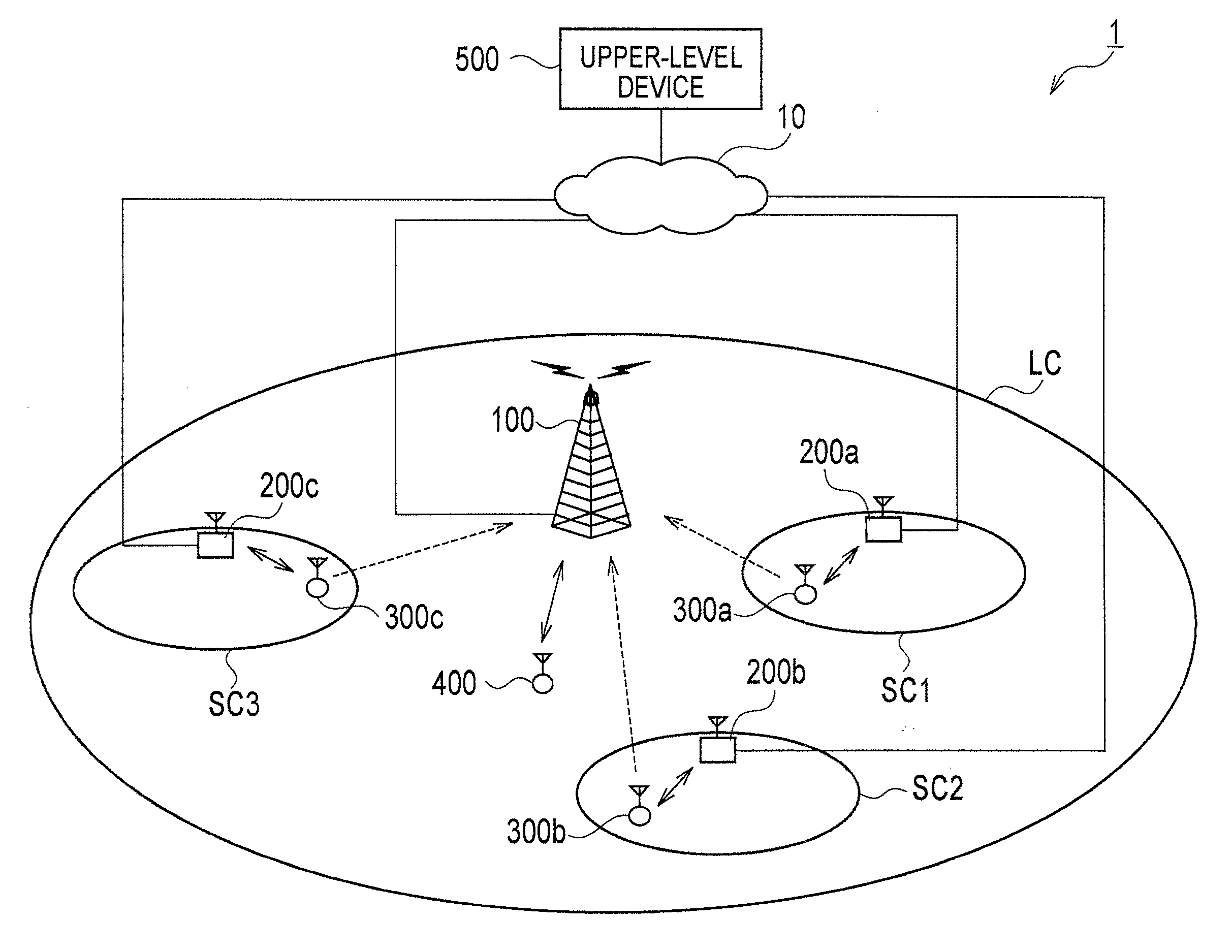
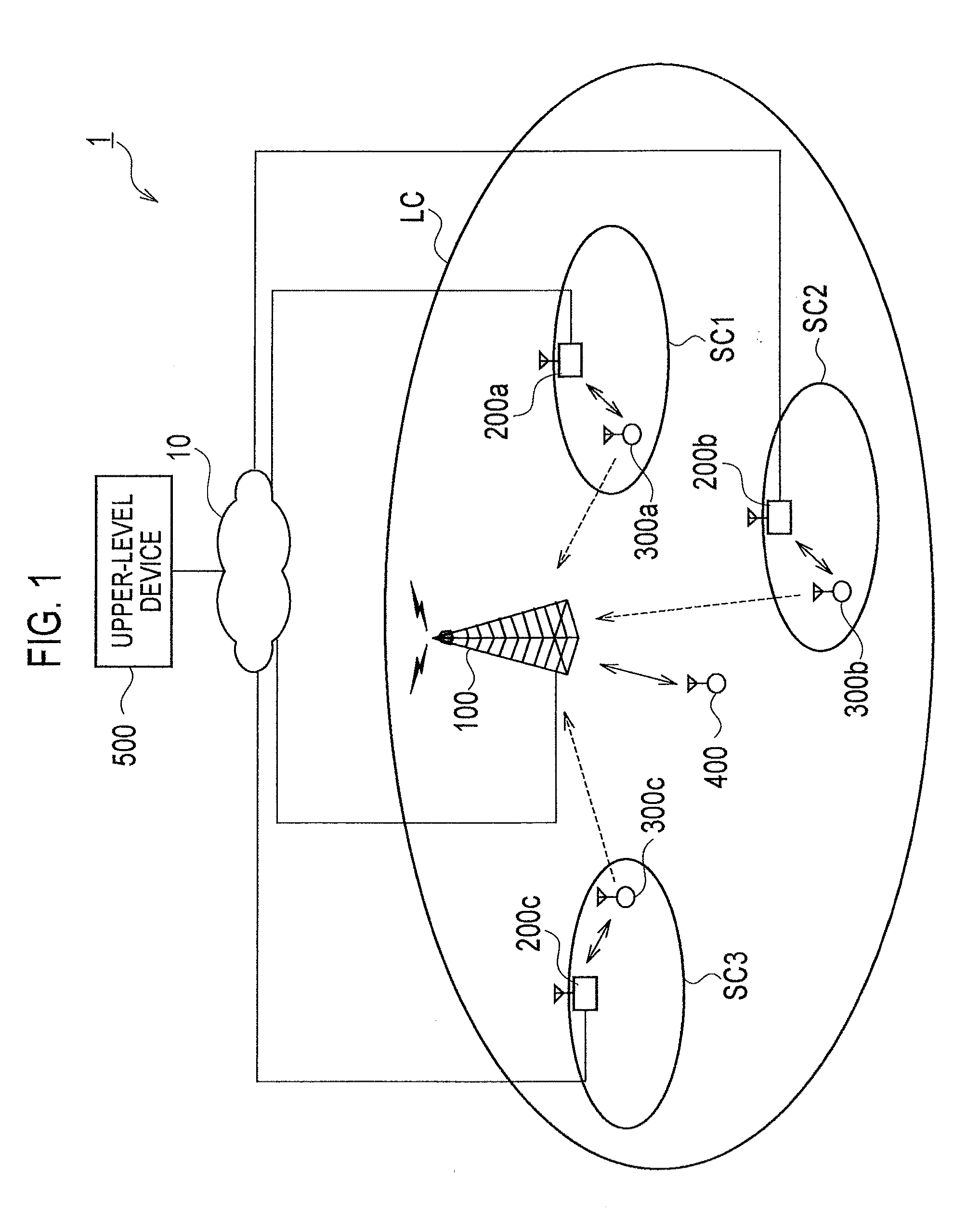
[0038]FIG. 1 is a schematic configuration diagram of a radio communication system 1 according the first embodiment. The radio communication system 1 has, for example, a configuration based on LIE Release 9 which is the 3.9th generation (3.9G) mobile phone system or a configuration based on LTE-Advanced which is positioned as the fourth generation (4G) mobile telephone system.

[0039]As shown in FIG. 1, the radio communication system 1 includes a large base station 100 forming a large cell LC and small cell base stations 200a to 200c which respectively form small cells SC1 to SC3. It should be noted that the number of the small cell base stations in th...

second embodiment

(2) Second Embodiment

[0116]Hereinafter, a second embodiment of the present invention is described. In the above-described first embodiment, the large cell base station 100 determines the upper-limit value Icap and notifies the small cell base station 200 of the upper-limit value Icap. However, in the second embodiment, an upper-level device 500 determines an upper-limit value Icap and notifies a small cell base station 200 of the upper-limit value Icap. In other words, in the second embodiment, the upper-level device 500 configures a network side device.

[0117]The second embodiment is described below focusing on portions different from those of the first embodiment.

(2.1) Configuration of Upper-Level Device

[0118]FIG. 9 is a block diagram showing a configuration of the upper-level device 500 according to the second embodiment.

[0119]As shown in FIG. 9, the upper-level device 500 according to the second embodiment is different from that of the first embodiment in that a controller 520 ha...


PUM


Abstract

A large cell base station 100 according to an embodiment is configured to form a large cell and includes: an upper-limit value determination unit 124 configured to determine an upper-limit value Icap of an amount of interference which is received by the large cell base station from each of the radio terminals based on a permissible value Itotal of a total amount of interference which is received by the large cell base station from the radio terminals and the number of the small cell base stations within the large cell; and a wired communication unit 140 configured to transmit upper-limit value information indicating the upper-limit value Icap determined by the upper-limit value determination unit 124 to the small cell base stations.

Description

CROSS-REFERENCE TO RELATED APPLICATION[0001]This application claims the benefit of priority under 35 U.S.C. section 119 of U.S. Provisional Application No. 61 / 248,359 filed Oct. 2, 2009, the disclosure of which is incorporated herein by reference in its entirety.BACKGROUND OF THE INVENTION[0002]1. Field of the Invention[0003]The present invention relates to a radio communication system, a network side device, a small cell base station, and a transmission power control method with which uplink transmission power of a radio terminal connected to a small cell base station is controlled.[0004]2. Description of the Related Art[0005]Recently, a small cell base station has attracted an attention. The small cell base station is a small-sized base station which forms a small cell of a communication area with a radius of several to several tens of meters and is capable of being installed indoor. Installing small cell base stations makes it possible to disperse the traffic of a large cell base...

Claims


Application Information

Patent Timeline
Patent Type & Authority Applications(United States)
IPC IPC(8): H04B7/00
CPCH04W52/242H04W52/04H04W52/367H04W52/243
Inventor NAKAMURA, KAZUTAKA
Owner KYOCERA CORP
Why Eureka
Try Eureka