
Calibration of Beamforming Nodes in a Configurable Monitoring Device System

a monitoring device and beamforming technology, applied in the field of communication and systems management technology, can solve the problems of affecting the cost-benefit analysis of installing and maintaining the system, many conventional systems are limited to the narrow scope of providing security functionality, and many conventional systems provide nothing more to the users of the system

Inactive Publication Date: 2011-04-07
CHECKPOINT SYST INC
View PDF36 Cites 255 Cited by
  • Summary
  • Abstract
  • Description
  • Claims
  • Application Information

AI Technical Summary

Benefits of technology

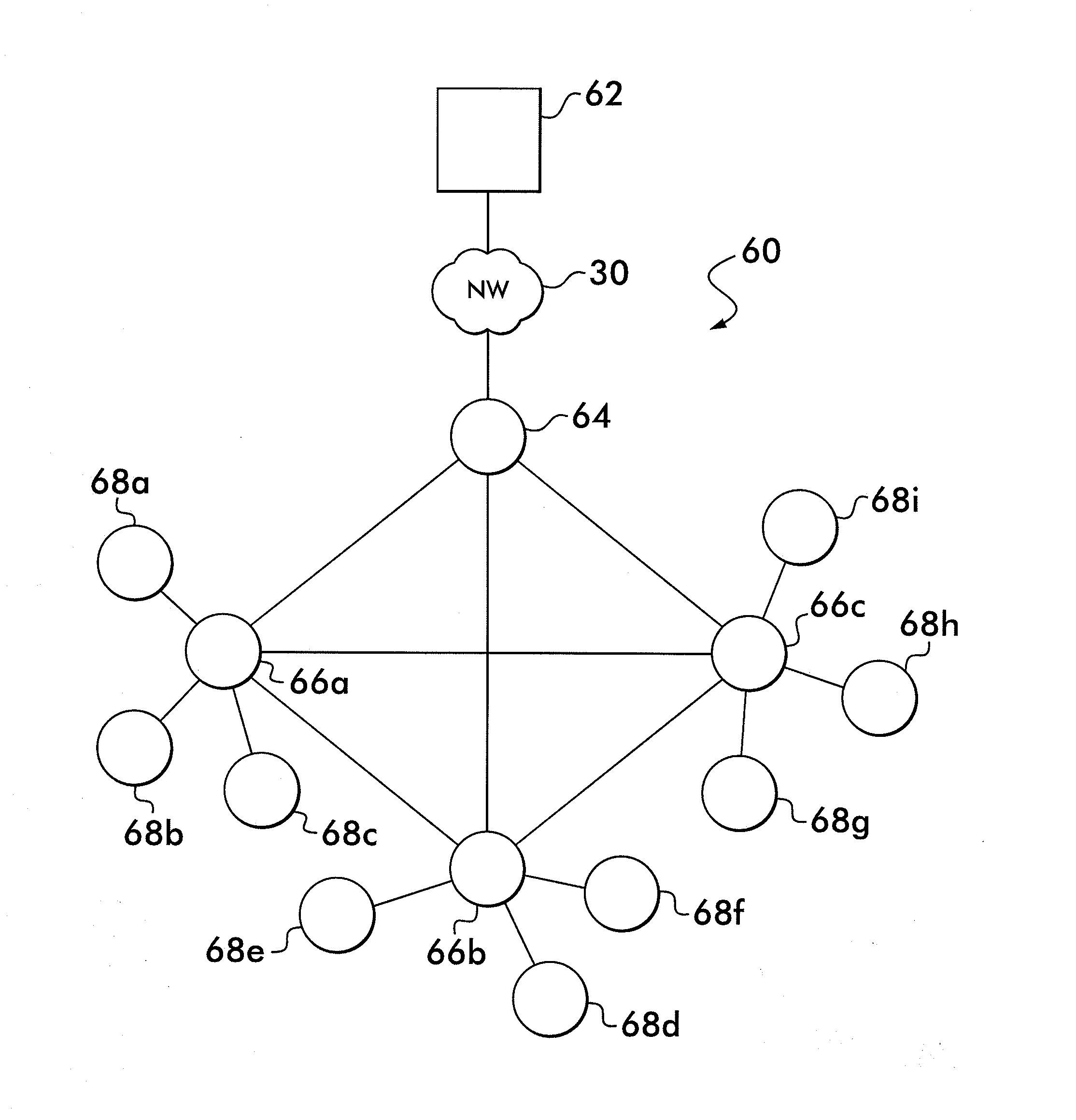
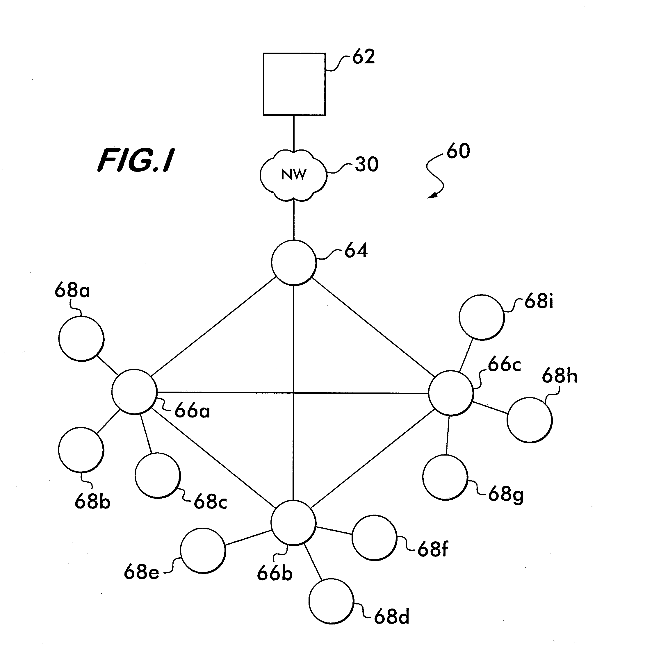
[0009]Some example embodiments of the present invention are therefore provided that support security system functionality, as well as, additional functionalities that would be beneficial to store owners, store managers, and customers. For example, some example embodiments support inventory and marketing functionality, as well as, advanced security functionality.
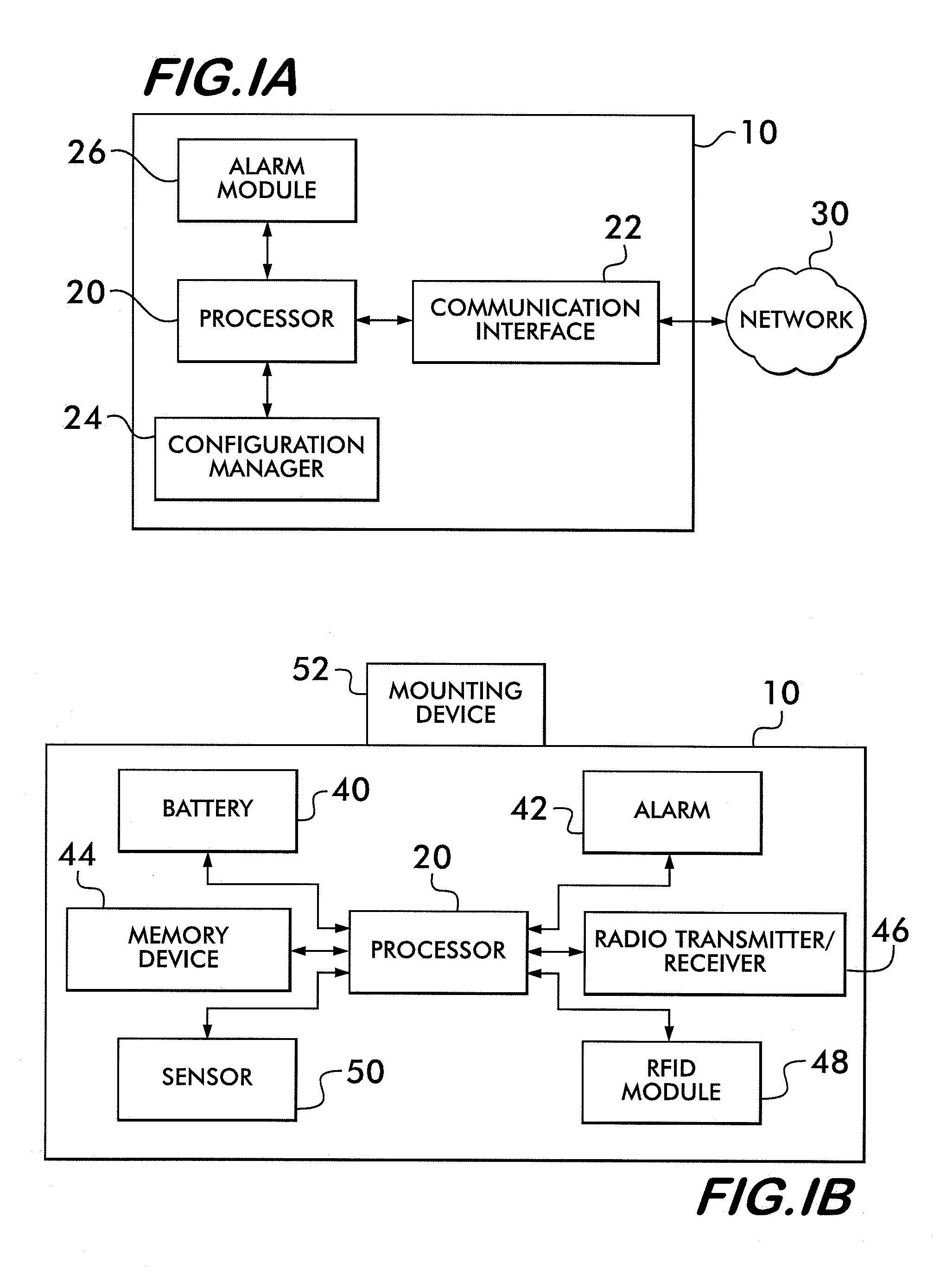
[0010]According to some example embodiments, a system is provided for managing configurable monitoring devices. A configurable monitoring device may be a microprocessor-based wireless communication device that can assume configurable roles or modes of operation within the system. A mode of operation may be implemented based on configuration information stored on the configurable monitoring device. The configuration information may be pre-loaded on the configurable monitoring device, or configurable monitoring devices may receive the configuration information via a wireless connection to a network.

Problems solved by technology

However, conventional systems are often limited to the narrow scope of providing security functionality.
Other than performing this important alarming functionality, many conventional systems provide nothing more to the users of the systems, such as store owners, store managers, and the like.
Additionally, when store owners are considering the purchase and installation of a conventional security system in a retail establishment, the limited functionality offered by the systems can detrimentally affect the cost-benefit analysis of installing and maintaining the system.

Method used


Image

  • Calibration of Beamforming Nodes in a Configurable Monitoring Device System
  • Calibration of Beamforming Nodes in a Configurable Monitoring Device System
  • Calibration of Beamforming Nodes in a Configurable Monitoring Device System

Examples


Embodiment Construction

[0004]A system for radio frequency identification of a tag in an interrogation zone, includes a calibration node disposed in the interrogation zone to measure a signal strength of radio frequency identification signals from a beamforming system and provide signal data in accordance with the signal strength. A reader node is configured to receive the signal data and adjust the radio frequency identification signals generated by the beamforming system based upon the signal data. At least one of the calibration node, the reader node and the beamforming system is a configurable monitoring system. The calibration node, the reader node, and the beamforming system are coupled in a feedback control loop. The beamforming system includes a plurality of beamforming nodes. A signal of at least one beamforming node is optimized in accordance with the feedback control loop. A signal to noise ratio of at least one beamforming node is optimized in accordance with the feedback control loop. A phase ...


PUM


Abstract

A system for radio frequency identification of a tag in an interrogation zone, includes a calibration node disposed in the interrogation zone to measure a signal strength of radio frequency identification signals from a beamforming system and provide signal data in accordance with the signal strength. A reader node is configured to receive the signal data and adjust the radio frequency identification signals generated by the beamforming system based upon the signal data. At least one of the calibration node, the reader node and the beamforming system is a configurable monitoring system. The calibration node, the reader node, and the beamforming system are coupled in a feedback control loop. The beamforming system includes a plurality of beamforming nodes. A signal of at least one beamforming node is optimized in accordance with the feedback control loop.

Description

CROSS-REFERENCE TO RELATED APPLICATIONS[0001]This application claims priority from provisional U.S. Patent Application No. 61 / 248,140 filed Oct. 2, 2009 entitled “COMMUNICATIONS SYSTEMS AND METHODS USING CONFIGURABLE MONITORING DEVICES,” U.S. patent application Ser. No. 11 / 702,980 filed Feb. 5, 2007 entitled “SYSTEMS AND METHODS OF BEAMFORMING IN RADIO FREQUENCY IDENTIFICATION APPLICATIONS” issued as U.S. Pat. No. 7,652,577, U.S. patent application Ser. No. 12 / 072,423 filed Feb. 25, 2008 entitled “LOCALIZING TAGGED ASSETS USING MODULATED BACKSCATTER,” and U.S. patent application Ser. No. 12 / 636,564 filed Dec. 11, 2009 entitled “SYSTEMS, METHODS AND APPARATUSES FOR MANAGING CONFIGURABLE MONITORING DEVICES.”TECHNOLOGICAL FIELD[0002]Embodiments of the present invention relate generally to communications and systems management technology.BACKGROUND[0003]Conventional retail security systems, such as electronic article surveillance (EAS) systems, operate effectively to prevent shoplifting...

Claims


Application Information

Patent Timeline
Patent Type & Authority Applications(United States)
IPC IPC(8): H04Q5/22
CPCG01S13/82H04W16/28G06K7/0095G06K7/10099G06K7/10217G06K7/10356G06K7/10475H04B7/0617H04Q2213/13095G01S2013/466G01S2013/468G01S7/4004G01S7/4052G01S7/4056G01S7/52004G08B13/2442G06K7/0008Y02D30/70
Inventor CLARE, THOMAS J.KRISHNAMURTHY, VENKAT
Owner CHECKPOINT SYST INC
Learn More