Eureka AIR delivers breakthrough ideas for toughest innovation challenges, trusted by R&D personnel around the world.

Method for operating an inverter, and inverter

a technology of inverter and inverter, applied in the direction of electric variable regulation, process and machine control, instruments, etc., can solve the problems of unnecessary switching loss of step-up converters and step-down converters, and achieve the effect of improving efficiency

Inactive Publication Date: 2011-04-07
DR JOHANNES HEIDENHAIN GMBH
View PDF5 Cites 126 Cited by
  • Summary
  • Abstract
  • Description
  • Claims
  • Application Information

AI Technical Summary

Benefits of technology

[0006]Example embodiments of the present invention provide a method for operating an inverter that allows for improved efficiency and provides an inverter by which this method may be implemented.
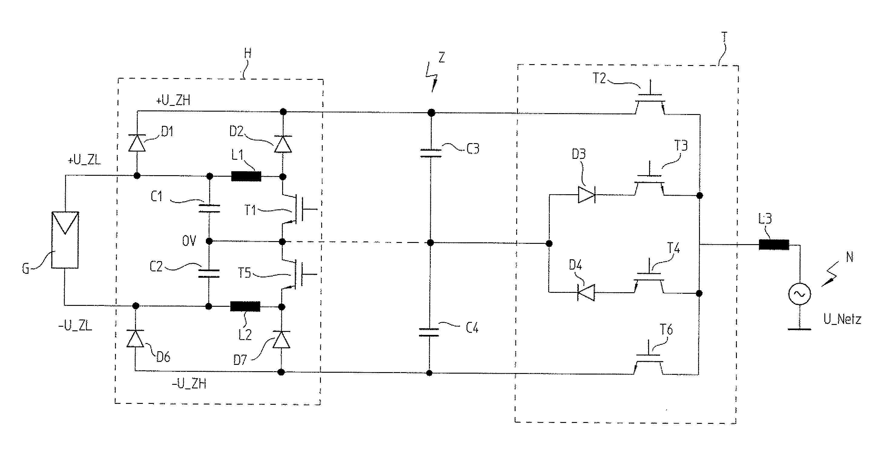
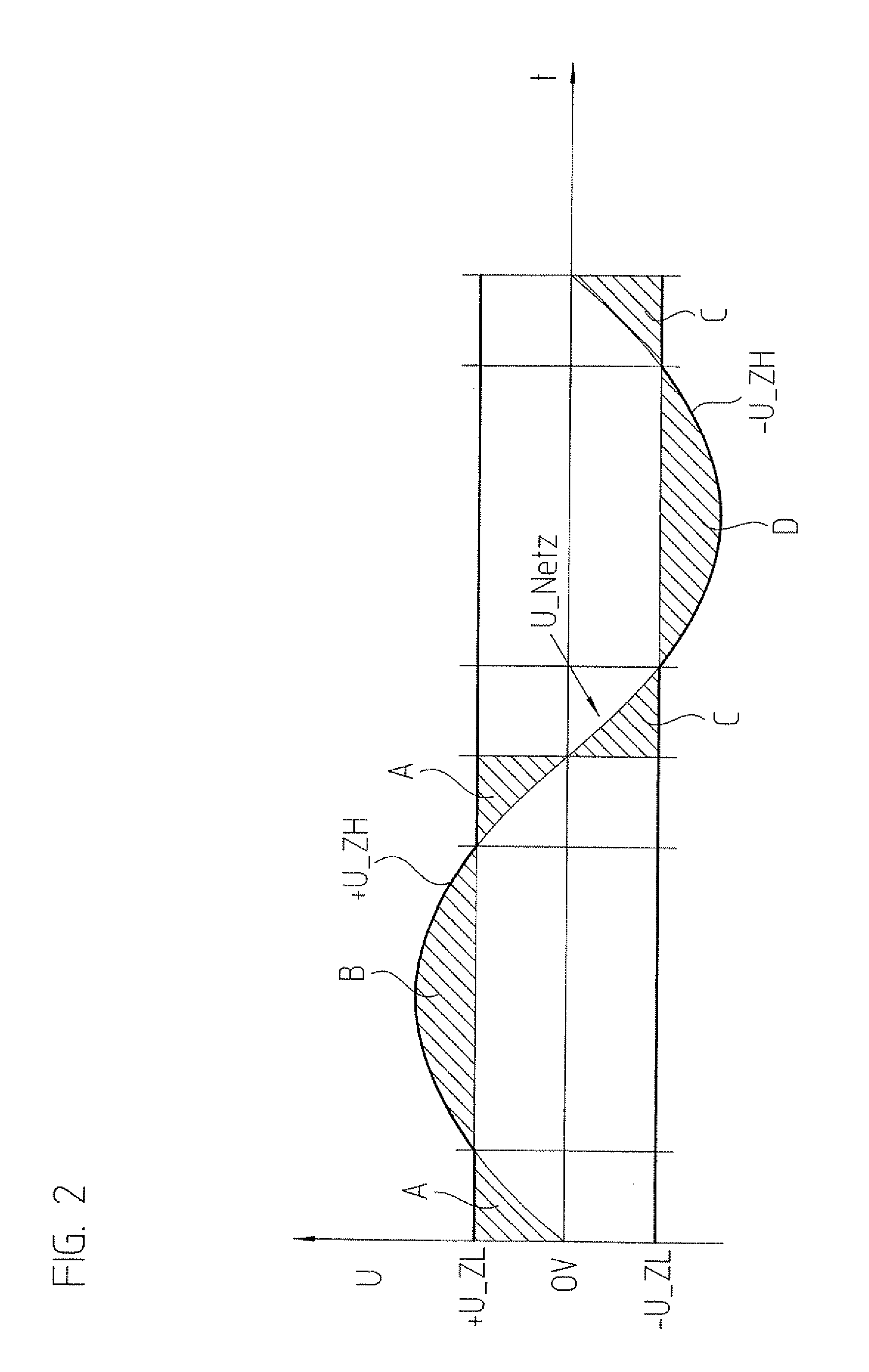
[0010]The inverter requires only one solar generator as a direct voltage source. The direct voltage is symmetrical with respect to a mid-voltage level. If the direct voltage supplied by the solar generator is lower than the currently required network voltage, then the step-up converters increase the generator voltage and thus the dynamic intermediate circuit voltage just to the required network voltage. This avoids having to take a step-down converter into operation at the same time. The latter is only put into operation if the generator voltage is above the currently required network voltage.

Problems solved by technology

In addition to the relatively high circuit expenditure, a disadvantage is that in this case the step-up converters and step-down converters produce unnecessary switching losses since in certain operating states the generator voltage is increased to a value from which the actually required voltage level must be generated using a step-down converter.

Method used


Image

  • Method for operating an inverter, and inverter
  • Method for operating an inverter, and inverter
  • Method for operating an inverter, and inverter

Examples


Embodiment Construction

[0027]A solar generator G is schematically illustrated in FIG. 1. This solar generator provides a direct voltage, which substantially depends on the current light intensity, but also on other parameters such as the operating temperature or the age of modules M. Two capacitors C1 and C2, which are connected in series and are parallel to generator G, create a mid-voltage level, which is designated here as 0V. This level may be grounded, but a grounding may also be omitted. Without grounding at the connection point of C1 and C2, small voltage ripples occur on generator G, a fact that makes it easier to maintain the operating point at the so-called maximum power point, at which solar generator G is most efficient, or which makes it possible to select the capacitance of the dynamic intermediate circuit to be smaller for the same MPP efficiency.

[0028]The positive voltage level +U_ZL of generator G is connected to a dynamic intermediate circuit Z via a first diode D1. In addition, +U_ZL is...


PUM


Abstract

In an inverter and a method for operating an inverter, the inverter includes a step-up converter circuit, a dynamic intermediate circuit, and a step-down converter circuit for converting a direct voltage of a direct voltage generator or string into an alternating voltage for supplying a network. The step-up converter circuit increases the direct voltage if the latter is lower than a peak-to-peak maximum of the network voltage, and the step-down converter circuit lowers a dynamic intermediate circuit voltage, as needed, to a lower voltage currently required in the network. The step-up converter circuit dynamically increases the direct voltage to the value currently required in the network and in the process temporarily supplies an approximately sinusoidal voltage curve for the intermediate circuit voltage.

Description

CROSS-REFERENCE TO RELATED APPLICATIONS[0001]The present application claims priority to Application No. 10 2009 047 936.6, filed in the Federal Republic of Germany on Oct. 1, 2009, which is expressly incorporated herein in its entirety by reference thereto.FIELD OF THE INVENTION[0002]The present invention relates to a method for operating an inverter and to an inverter suitable for this purpose.BACKGROUND INFORMATION[0003]Inverters are used to convert an existing direct voltage into an alternating voltage, in order to supply the latter to an alternating current network, for example. In particular in the application in the area of photovoltaics, the highest possible efficiencies are required in this connection.[0004]German Published Patent Application No. 10 2006 010 694 describes a solar inverter, in which two direct voltage sources or solar generators are connected in series, and the connection point forms a first voltage level or a mid-voltage. The two external terminals of the so...

Claims


Application Information

Patent Timeline
IPC IPC(8): G05F1/10
CPCH02J3/383H02M7/48H02M7/487Y02E10/563H02M2001/007H02J2300/24H02J3/381Y02E10/56H02J3/46H02M1/007
Inventor SCHOENLINNER, MARKUSHUBER, NORBERT
Owner DR JOHANNES HEIDENHAIN GMBH
Why Eureka
Eureka Blog
Learn More