
Spectrum-splitting and wavelength-shifting photovoltaic energy converting system suitable for direct and diffuse solar irradiation

Inactive Publication Date: 2011-04-07
DETAB SERGIY
View PDF10 Cites 10 Cited by
  • Summary
  • Abstract
  • Description
  • Claims
  • Application Information

AI Technical Summary

Benefits of technology

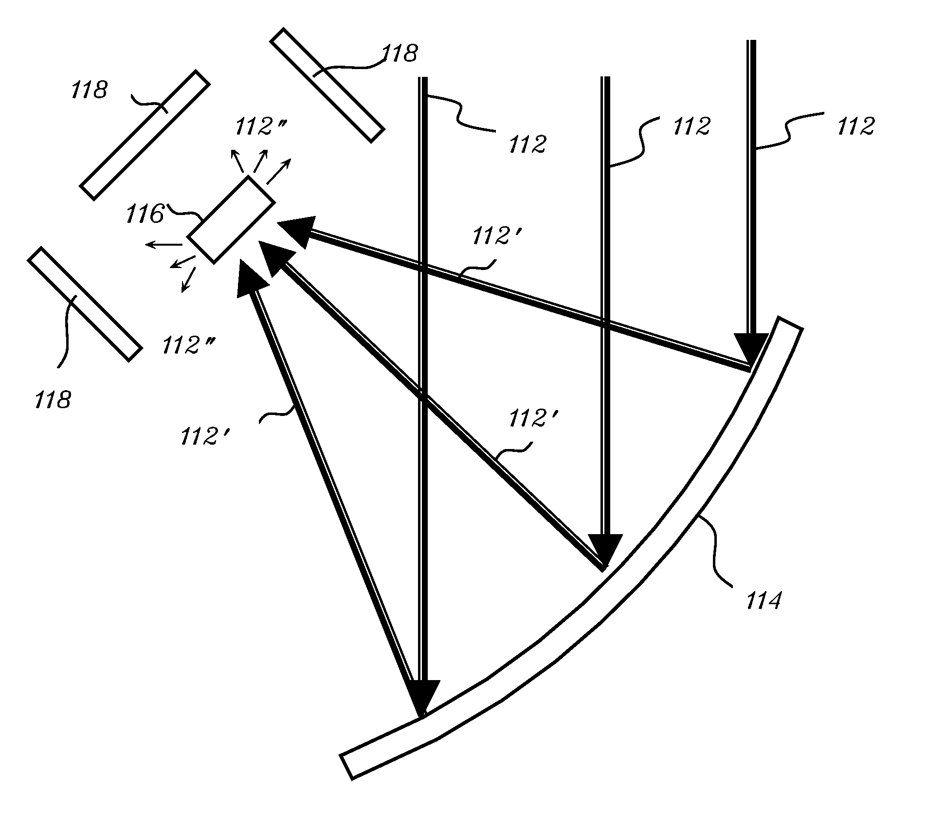
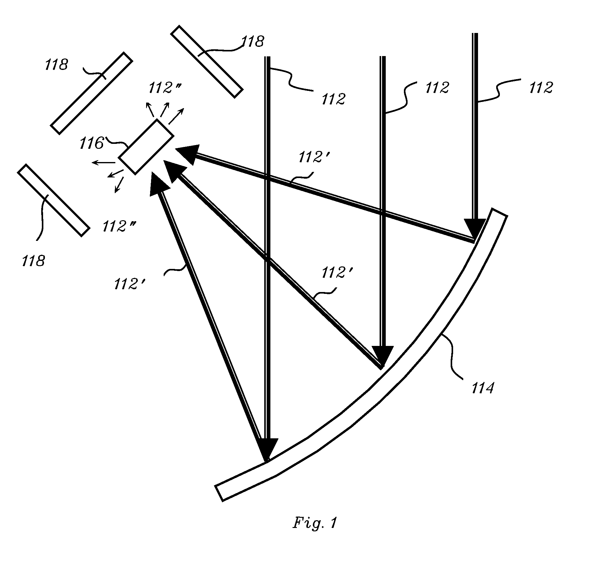
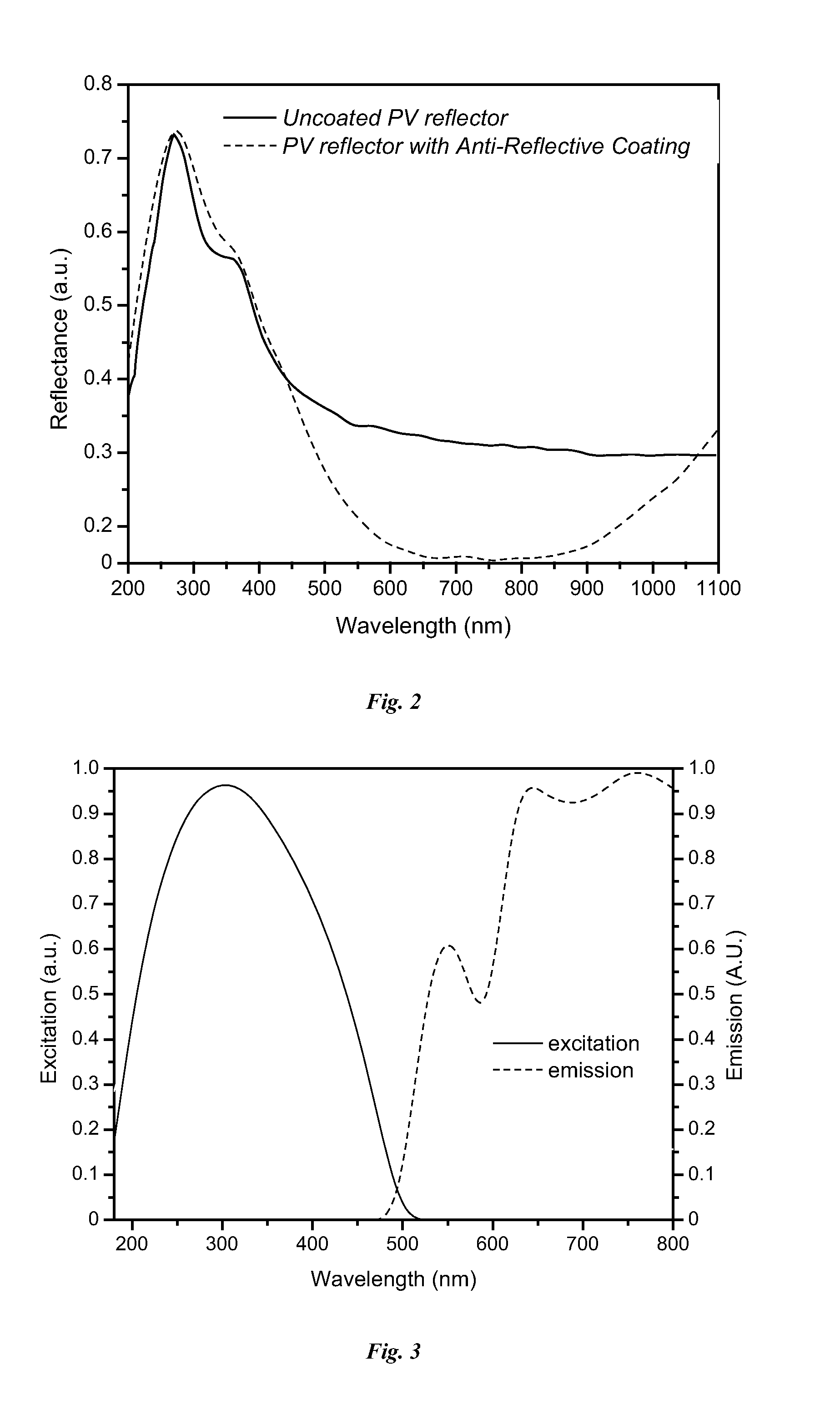
[0019]In accordance with another aspect of the invention, there is provided an improved inherent spectrum-splitting photovoltaic concentrator system equipped with a curved reflector that receives broadband solar radiation and absorbs and converts into electricity those photons with lower bandgap energies of solar spectrum and reflects and concentrates higher bandgap energy solar radiation in a radiation path toward a predetermined spatially confined area of use. A first photovoltaic means, which is preferably shaped into spectrally selective reflector from plastically deformed silicon wafer, absorbs and converts into electricity photons falling below the first predetermined bandgap of energy defining longwave visible radiation, so that it is predominantly photons with higher bandgap energy that comprise the stream that is reflected and concentrated by the first photovoltaic means towards the second photovoltaic means or thermal absorber. In the preferred embodiment, the first photovoltaic means converts into electricity many of those photons with energies less than a predetermined energy level and reflects higher energy photons. Reflected high energy photons are concentrated by this first photovoltaic means into a radiation stream that is partially transmitted, absorbed and converted by the fluorescent material into a radiation stream that carries lower bandgap energy photons toward the second photovoltaic means. In its simplest sense, an apparatus for the spectral splitting and collection of broadband solar radiation comprises a curved photovoltaic receiver, concentrating at least part of incoming radiation stream towards the fluorescent waveguiding material which is optically coupled to a second photovoltaic element. Thus, the present invention discloses a novel means of splitting the incoming combination of diffuse and direct solar radiation into energy bands and directing the energy toward corresponding photovoltaic cells with improved photovoltaic conversion. Accordingly, an improved solar concentrator provides user-friendly, yet economical means of increasing the efficiency of photovoltaic conversion under direct and diffuse solar radiation.

Problems solved by technology

However, the system of Winston et al. has a narrow field of view such that it suffers from low efficiency under overcast conditions when the incident light is diffuse.
One disadvantage of such device is that the focusing mirror non-selectively delivers both short-wave and long-wave solar radiation while only radiation within a limited wavelength range that effectively stimulates fluorescence is transmitted through the coupled optical wave guide to the point of use.
Customarily these devices have not been known to operate in a mode where solar radiation is delivered to both thermal absorbers and photovoltaic converters at once.
However, it is apparent that the disclosed system was applicable only to concentrate a direct solar light stream (i.e. highly collimated solar radiation) and not intended for the collection and conversion of diffuse radiation, as the metallized parabolic reflector is positioned to only receive a direct solar light stream.
However, this patent and reference do not disclose using plastic deformation to produce spectrum-splitting and wavelength-shifting photovoltaic energy converting systems.
However, the disclosure of such potential application does not disclose using shaped silicon to produce spectrum-splitting and wavelength-shifting photovoltaic energy converting systems.
However, Wallace, JR. does not disclose producing spectrum-splitting and wavelength-shifting photovoltaic energy converting systems.
However, such commercially available solar panels do not constitute a spectrum-splitting and wavelength-shifting photovoltaic energy converting system.

Method used


Image

  • Spectrum-splitting and wavelength-shifting photovoltaic energy converting system suitable for direct and diffuse solar irradiation
  • Spectrum-splitting and wavelength-shifting photovoltaic energy converting system suitable for direct and diffuse solar irradiation
  • Spectrum-splitting and wavelength-shifting photovoltaic energy converting system suitable for direct and diffuse solar irradiation

Examples


Embodiment Construction

[0033]An energy converting system includes: (a) first means for receiving incident solar radiation, converting to electricity those photons of said incident solar radiation having energies less than a predetermined bandgap energy, and reflecting reflected photons having energies greater than said predetermined bandgap; (b) second means for producing, in response to said reflected photons, wavelength-shifted photons having energies less than said predetermined bandgap energy; and (c) third means for converting into electricity said wavelength-shifted photons.

[0034]Referring to FIG. 1, the system according to a first embodiment of the invention is illustrated. The system illustrated in FIG. 1 relates to solar collectors, specifically to solar electromagnetic radiation concentrators that allow users to convert diffuse and direct solar radiation into more useful forms of energy by employment of both spectral splitting and redirecting of incoming solar radiation towards points of more ef...


PUM


Abstract

A photovoltaic energy converting system includes: (a) a first photovoltaic converter operable to receive incident solar radiation and convert to electricity those photons of the incident solar radiation having energies less than a predetermined bandgap energy; (b) a fluorescing member positioned for receiving reflected photons having reflected from the first photovoltaic converter, the fluorescing member being operable to produce, in response to the reflected photons, wavelength-shifted photons having energies less than the predetermined bandgap energy; and (c) a second photovoltaic converter operable to convert into electricity the wavelength-shifted photons. The system is thereby advantageously suitable for operation under either direct or diffuse solar irradiation.

Description

CROSS-REFERENCE TO RELATED APPLICATIONS[0001]This application claims priority of provisional application 61 / 247,629 filed on Oct. 1, 2009, the entire contents of which are hereby incorporated by reference.BACKGROUND OF THE INVENTION[0002]1. Field of Invention[0003]This invention relates to the conversion of solar radiation to electricity and, in particular, to a spectrum-splitting and wavelength-shifting photovoltaic energy converting system suitable for direct and diffuse solar irradiation.[0004]2. Description of Related Art[0005]A photovoltaic device for converting sunlight into electricity is exposed to direct solar radiation predominantly impinging on it from a single point source, namely the sun such as found on a clear and sunny day, and to diffuse solar radiation impinging on it from a multitude of angles at relatively uniform intensity, such as occurs on a cloudy day when direct sunlight is blocked. Some photovoltaic systems attempt to collect solar radiation and to convert ...

Claims


Application Information

Patent Timeline
IPC IPC(8): H01L31/055
CPCH01L31/055H01L31/0547Y02E10/52
Inventor DETS, SERGIY
Owner DETAB SERGIY
Learn More