
Planetary gear unit for a gearbox for a wind turbine

a technology of planetary gear unit and wind turbine, which is applied in the direction of bearings, toothed gearings, motors, etc., can solve the problems of high cost requirements of the manufacturing process design limits, and the size of the planetary gear unit components keeps increasing, so as to achieve the effect of adjusting the manufacturing cost of the planetary gear uni

Inactive Publication Date: 2011-03-31
HANSEN TRANSMISSIONS INT NV
View PDF0 Cites 16 Cited by
  • Summary
  • Abstract
  • Description
  • Claims
  • Application Information

AI Technical Summary

Benefits of technology

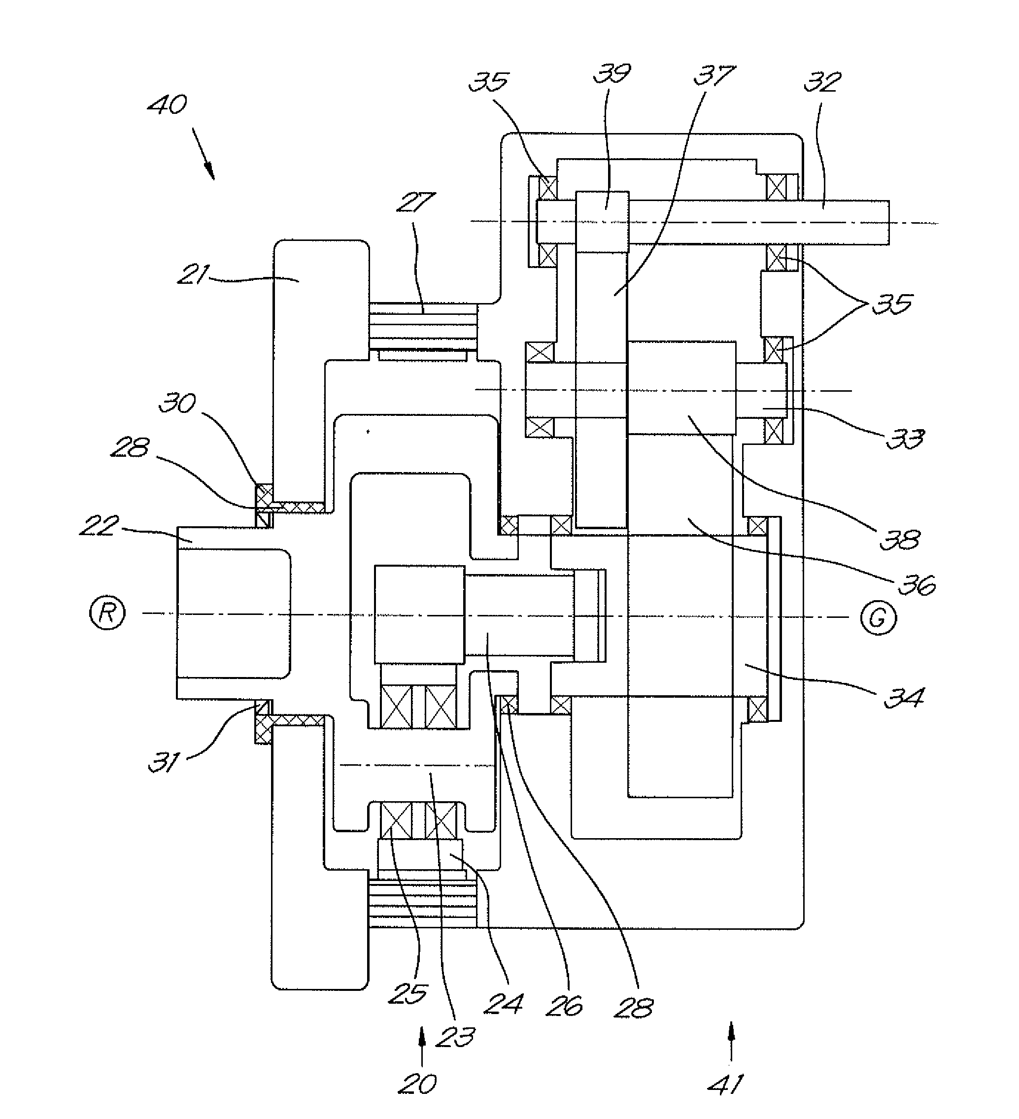
[0014]Hence, the present invention provides a planetary gear unit comprising a combination of rolling bearings and sliding bearings in a same unit. By using sliding bearings which are different from sliding bearings currently used as planet carrier bearings in combination with rolling bearings at other locations in the planetary gear unit, manufacturing costs of a planetary gear unit according to embodiments of the invention can be significantly decreased.

Problems solved by technology

For multi-megawatt wind turbines, available roller bearings for use in planetary gear units of a gearbox may provide high cost requirements to the manufacturing process of the planetary gear unit because, as a consequence of growing needs for multi-megawatt turbines, sizes of planetary gear unit components keeps increasing.
In case of planetary carrier bearings, these design limits could originate from failure modes such as, for example, slip, wear or mixed friction.
The larger rolling bearings, which are now used for supporting planet carriers in planetary gear units, become, the higher their cost becomes and thus the higher the costs for manufacturing the planetary gear unit are.
Unfortunately there are no standard bearings available in sizes and designs required for gearboxes for multi-megawatt wind turbines.
However, such big sliding bearings are very expensive and thus consequently increase costs for manufacturing planetary gear units.

Method used


Image

  • Planetary gear unit for a gearbox for a wind turbine
  • Planetary gear unit for a gearbox for a wind turbine
  • Planetary gear unit for a gearbox for a wind turbine

Examples


Embodiment Construction

[0035]The present invention will be described with respect to particular embodiments and with reference to certain non-limiting drawings. It has to be understood that the invention is not limited thereto but is only limited by the claims. For illustrative purposes, the size of some of the elements in the drawings may be exaggerated and not drawn on scale.

[0036]Terms such as “comprising” and “coupled” are not to be interpreted as limiting the invention in any way. The term “comprising”, used in the claims, should not be interpreted as being restricted to the means listed thereafter; it does not exclude other elements or steps. Similarly, it is to be noticed that the term “coupled”, also used in the claims, should not be interpreted as being restricted to direct connections only.

[0037]While some embodiments described herein include some but not other features included in other embodiments, combinations of features of different embodiments are meant to be within the scope of the invent...


PUM


Abstract

A planetary gear unit (20) for a gearbox (40) for a wind turbine includes a housing (21) and a planet carrier (22) provided with planet shafts (23) distributed uniformly around a planet carrier's axis for rotatably supporting planet gears (24) which are mounted between a sun gear (26) and a ring gear (27) for mutual interaction and which are supported by rolling bearings (25). The planet carrier is rotatably mounted in the housing with sliding bearings (28). By using sliding bearings which are different from existing classical sliding bearings which are currently used for rotatably mounting the planet carrier in the housing in combination with the use of rolling bearings for supporting other parts of the planetary gear unit, costs of the planetary gear unit may significantly be reduced. A gearbox including such a planetary gear unit and a wind turbine including such a gearbox are also described.

Description

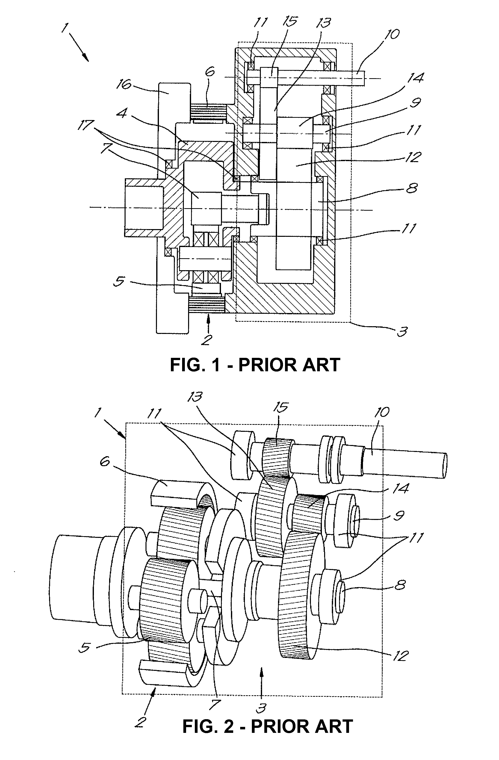
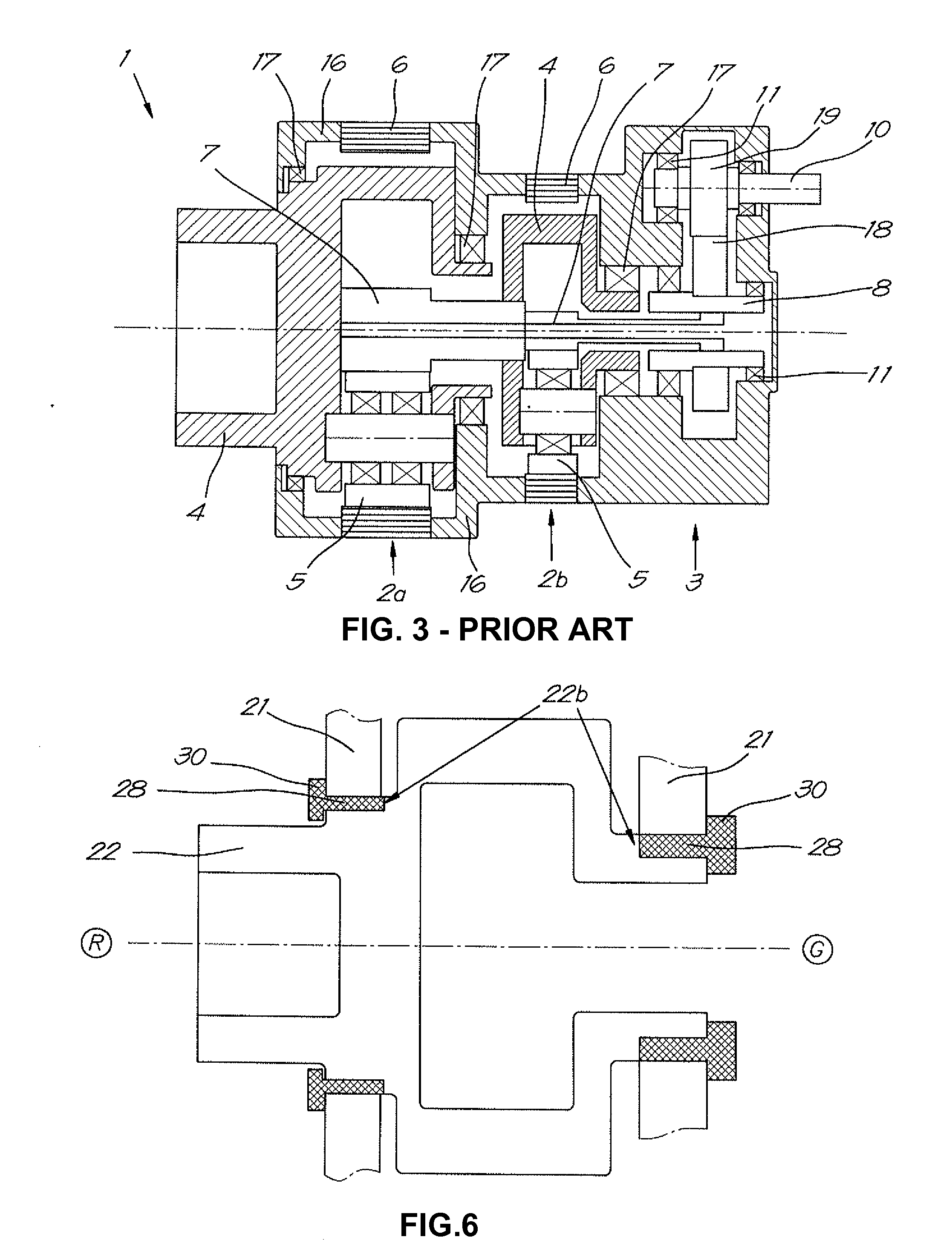
TECHNICAL FIELD OF THE INVENTION[0001]The present invention relates to a planetary gear unit for a gearbox for a wind turbine. The present invention furthermore relates to a gearbox comprising such planetary gear unit and to a wind turbine comprising such a gearbox.BACKGROUND OF THE INVENTION[0002]As wind energy business becomes more and more important, gearbox concepts are thoroughly studied nowadays. Known concepts of gearboxes for wind turbines may comprise at least one planetary gear unit and a parallel gear unit for connecting the planetary gear unit to the generator of the wind turbine.[0003]FIG. 1 and FIG. 2 schematically illustrate one type of gearbox 1 for a wind turbine according to the prior art. In this example, the gearbox 1 comprises one planetary gear unit 2 and a two-stage parallel gear unit 3. The planetary gear unit 2 comprises a planet carrier 4 which supports a plurality of planet gears 5. The planetary gear unit 2 furthermore comprises a ring gear 6 and a sun ge...

Claims


Application Information

Patent Timeline
IPC IPC(8): F16H3/44
CPCF03D11/02F05B2260/40311F16H2057/085F16H57/082Y02E10/722F16H37/041F03D15/00F16C17/02F16C2361/61Y02E10/72F03D80/70F03D15/10
Inventor DIRK, LEIMANN
Owner HANSEN TRANSMISSIONS INT NV
Learn More