
Positive-Working Photoimageable Bottom Antireflective Coating

a technology of anti-reflective coating and positive working, which is applied in the direction of photosensitive materials, photomechanical equipment, instruments, etc., can solve the problems of damage to the substrate, inability to precisely transfer the photoresist pattern to the substrate,

Active Publication Date: 2011-03-31
MERCK PATENT GMBH
View PDF99 Cites 48 Cited by
  • Summary
  • Abstract
  • Description
  • Claims
  • Application Information

AI Technical Summary

Benefits of technology

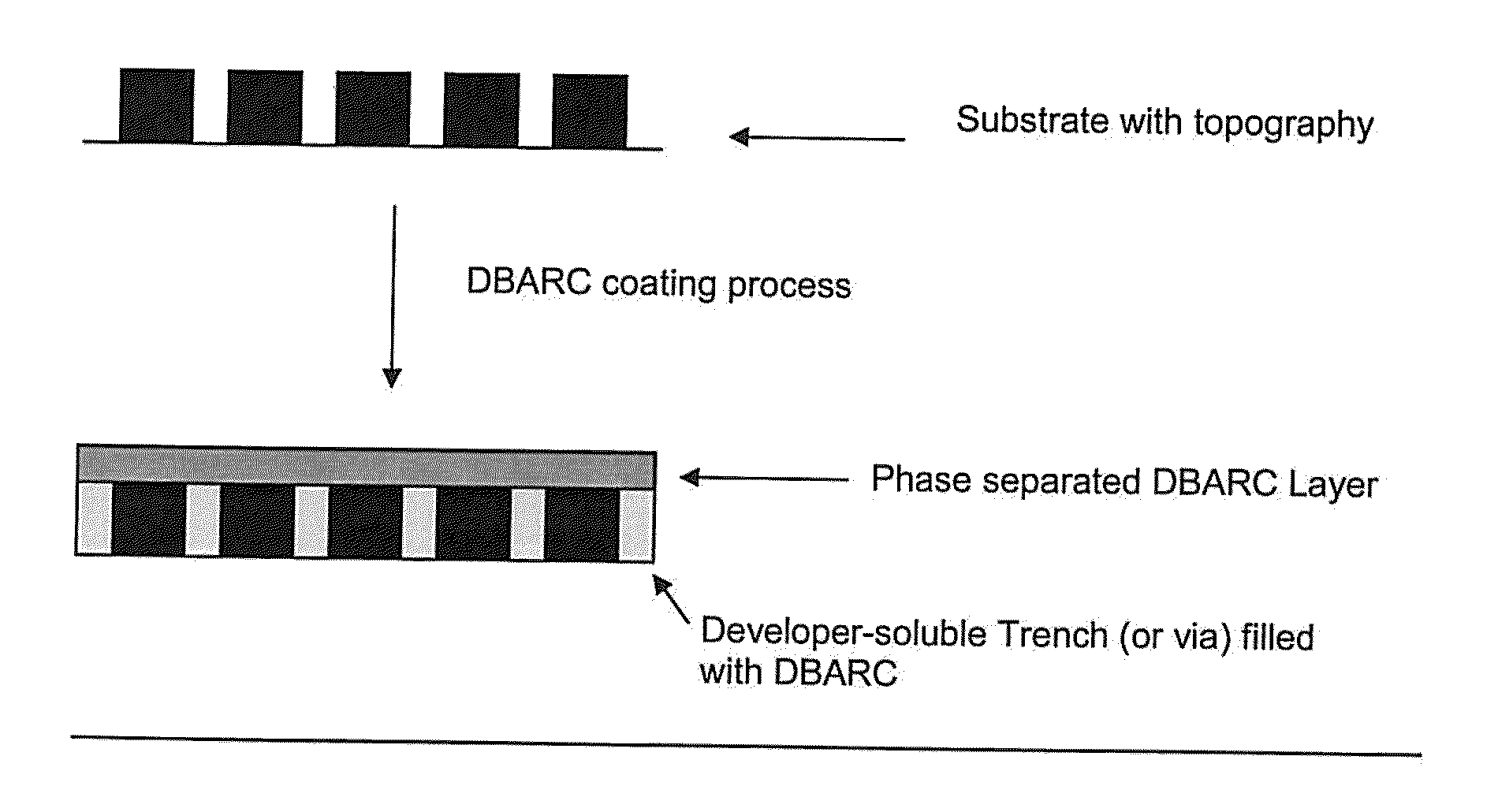
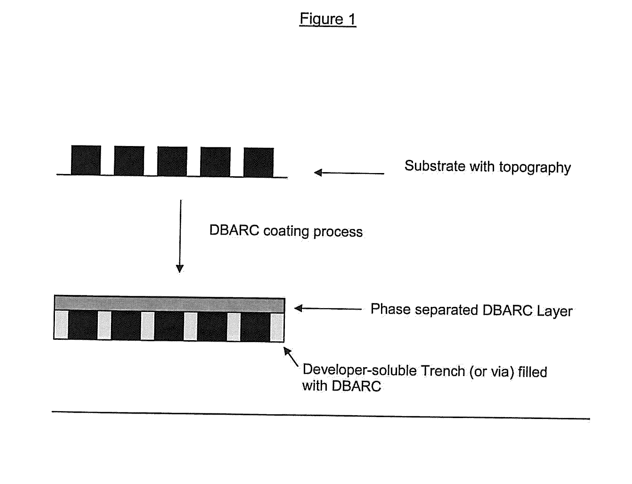
[0011]The present invention relates to a novel absorbing, photoimageable and aqueous alkali developable positive image-forming antireflective coating composition comprising (i) a polymer A soluble in a coating solvent and comprises a chromophore, an optional fluorinated group, crosslinkable group such as a hydroxyl and / or a carboxyl moiety, and optionally a cleavable group which under acid or thermal conditions produces a functionality which aids in promoting the solubility of the polymer in an aqueous alkaline solution; (ii) at least one photoacid generator; (iii) a crosslinking agent; (iv) optionally, a thermal acid generator, (v) a polymer B which is soluble in an aqueous alkaline solution prior to development, where polymer B is non-miscible with polymer A and soluble in the coating solvent, and; (vi) a coating solvent composition; and (vii) optionally, a quencher.

Problems solved by technology

Thus, treatment of an exposed positive-working photoresist with a developer causes removal of the exposed areas of the photoresist coating and the formation of a positive image in the coating, thereby uncovering a desired portion of the underlying substrate surface on which the photoresist composition was deposited.
In addition, photoresist patterns may be damaged or may not be transferred exactly to the substrate if the dry etch rate of the antireflective coating is similar to or less than the etch rate of the photoresist coated on top of the antireflective coating.
The etching conditions for removing the organic coatings can also damage the substrate.

Method used


Image

  • Positive-Working Photoimageable Bottom Antireflective Coating
  • Positive-Working Photoimageable Bottom Antireflective Coating
  • Positive-Working Photoimageable Bottom Antireflective Coating

Examples


example 1

Synthesis of (PQMA / AMMA / MA-BTHB-OH) terpolymer

[0046]

[0047]In a 250 mL round bottom flask equipped with a stirrer, thermocouple and reflux condenser under nitrogen, 9-anthracenylmethyl methacrylate (AMMA, 4.34 g), 4-hydroxyphenyl methacrylate (PQMA, 8.410 g), 1-hydroxy-1,1-bis(trifluoromethyl)-3-butyl methacrylate (MA-BTHB-OH, 4.87 g), 2,2′-azobis(2-methylpropionitrile) (AIBN, 0.86 g), and tetrahydrofuran (THF, 106.50 g) were added and stirred to dissolve the solids. The mixture was heated to 65° C. for 5 hours, cooled for 30 minutes to room temperature, then precipitated into hexanes (800 mL). The precipitate was collected by vacuum filtration, dissolved in tetrehyrofuran (THF) (90 mL), and precipitated in hexanes (800 mL) once, again. The precipitate was collected by vacuum filtration and dried at 45° C. to yield a white solid (14.4 g, 79%). Polymer molecular weight and NMR composition are provided in Table 1.

The polymer had n&k values at 248 nm of 1.56 & 0.33 and 1.76 & 0.46 at 19...

example 2

Synthesis of PQMA / EAdMA / PFPMA terpolymer

[0048]In a 250 mL round bottom flask equipped with a stirrer, thermocouple and reflux condenser under nitrogen, 2-ethyladamantylmethacrylate (EAdMA, 7.75 g), 4-hydroxyphenyl methacrylate (PQMA, 16.69 g), 2,2,3,3,3-pentafluoropropylmethacrylate (PFPMA, 6.81 g), 2,2′-azobis(2-methylpropionitrile) (AIBN, 6.25 g), and tetrahydrofuran (THF, 87.50 g) were added and stirred to dissolve. The mixture was heated to 65° C. for 5 hours, cooled for 30 minutes to room temperature, then precipitated into hexanes (875 mL). The precipitate was collected by vacuum filtration, dissolved in THF (85 mL), and precipitated in hexanes (875 mL) once again. Finally, the precipitate was redissolved in 80 mL of methanol and precipitated in water (875 mL). The precipitate was collected by vacuum filtration and dried at 45° C. to yield a white solid (23.14 g, 74%). Polymer molecular weight and NMR composition are provided in Table 1.

The polymer had n&k values at 193 nm of ...

example 3

PQMA / PFPMA / MA-3,5-HFA-CHOH terpolymer

[0049]In a 250 mL round bottom flask equipped with a stirrer, thermocouple and reflux condenser under nitrogen, 3,5-bis(hexafluoro-2-hydroxy-2-propyl)cyclohexyl methacrylate (MA-3,5-HFA-CHOH, 8.28 g), 4-hydroxyphenyl methacrylate (PQMA, 11.78 g), 2,2,3,3,3-pentafluoropropylmethacrylate (PFPMA, 6.02 g), 2,2′-azobis(2-methylpropionitrile) (AIBN, 3.91 g), and tetrahydrofuran (THF, 70.00 g) were added and stirred to dissolve. The mixture was heated to 65° C. for 5 hours, cooled for 15 minutes, quenched with methanol (3 mL), further cooled to room temperature, and then precipitated into hexanes (750 mL). The precipitate was collected by vacuum filtration, dissolved in THF (85 mL), and precipitated in hexanes (750 mL) once again. Finally, the precipitate was redissolved in 70 g of methanol and precipitated in water (750 mL). The precipitate was collected by vacuum filtration and dried at 45° C. to yield a white solid (22.19 g, 85%). The n & k values of...


PUM


Abstract

The invention relates to a photoimageable antireflective coating composition capable of forming a pattern by development in an aqueous alkaline solution, comprising, (i) a polymer A soluble in a coating solvent and comprises a chromophore, a crosslinking moiety, and optionally a cleavable group which under acid or thermal conditions produces a functionality which aids in the solubility of the polymer in an aqueous alkaline solution and; (ii) at least one photoacid generator; (iii) a crosslinking agent; (iv) optionally, a thermal acid generator; (v) a polymer B which is soluble in an aqueous alkaline solution prior to development, where polymer B is non-miscible with polymer A and soluble in the coating solvent, and; (vi) a coating solvent composition, and (vii) optionally, a quencher. The invention also relates to a process for imaging the antireflective coating.

Description

FIELD OF INVENTION[0001]The present invention relates to novel positive-working, photoimageable, and aqueous developable antireflective coating compositions and their use in image processing by forming a layer of the novel developer soluble antireflective coating composition between a reflective substrate and a photoresist coating. Such compositions are particularly useful in the fabrication of semiconductor devices by photolithographic techniques, especially those requiring exposure with deep ultraviolet radiation.DESCRIPTION[0002]Photoresist compositions are used in microlithography processes for making miniaturized electronic components such as in the fabrication of computer chips and integrated circuits. Generally, in these processes, a thin coating of a film of a photoresist composition is first applied to a substrate material, such as silicon wafers used for making integrated circuits. The coated substrate is then baked to evaporate any solvent in the photoresist composition a...

Claims


Application Information

Patent Timeline
IPC IPC(8): G03F7/00G03C1/00
CPCG03F7/091G03F7/0046G03F7/11
Inventor PADMANABAN, MUNIRATHNACHAKRAPANI, SRINIVASANHOULIHAN, FRANCIS M.MIYAZAKI, SHINJING, EDWARDNEISSER, MARK O.
Owner MERCK PATENT GMBH
Learn More