Fuel cell comprising separator with protrusions in zigzag-pattern

a separator and zigzag-pattern technology, applied in the field of fuel cells, can solve the problems of separator deformation, power generation efficiency lowering undesired, small contact area between separator and mea, etc., and achieve the effect of improving power generation efficiency

Inactive Publication Date: 2011-03-31
HONDA MOTOR CO LTD
View PDF9 Cites 2 Cited by
  • Summary
  • Abstract
  • Description
  • Claims
  • Application Information

AI Technical Summary

Benefits of technology

[0009]The present invention solves the problems of this type, and an object of the present invention is to provide a fuel cell in which the desired strength of the separator itself is effectively maintained, the contract area between the separator and the electrolyte electrode assembly is increased, and flowing of the reactant gas without being used is suppressed to achieve improvement in the power generation efficiency.
[0016]In the present invention, in the sandwiching section, a large number of projections are arranged efficiently in comparison with the structure where projections are arranged in a matrix pattern. Thus, with the simple structure, warpage of the separator is suppressed, and the strength against deformation is improved, and improvement in the quality is achieved. Further, since the contact area of the sandwiching section with the electrolyte electrode assembly is increased, the IR losses are reduced, and improvement in the power generation efficiency is achieved. Moreover, since the projections are provided close to each other, flowing of the reactant gas without being used is suppressed, also resulting in the improved power generation efficiency.

Problems solved by technology

However, in Japanese Laid-Open Patent Publication No. 63-266777, since the cutouts are formed in the corrugated plate, the contact area between the separator and the MEA tends to be small.
Therefore, the reactant gas tends to flow through without being consumed, and the power generation efficiency may be lowered undesirably.
Warpage or the like occurs easily in the separator, and the separator is deformed.
WO 00 / 03446, though the projections 2 are arranged in a zigzag pattern on the separator substrate 1, due to the structure of the fuel cell as a whole, it may not be possible to effectively increase the contract area with the MEA.
Thus, improvement in the power generation efficiency cannot be achieved.
Further, it may not be possible to sufficiently suppress warpage of the separator and deformation of the separator.
Therefore, it is difficult to effectively increase the contact area with the MEA.
Further, warpage and deformation of the separator cannot be suppressed, and the reactant gas may flow through without being consumed.

Method used


Image

  • Fuel cell comprising separator with protrusions in zigzag-pattern
  • Fuel cell comprising separator with protrusions in zigzag-pattern
  • Fuel cell comprising separator with protrusions in zigzag-pattern

Examples


first embodiment

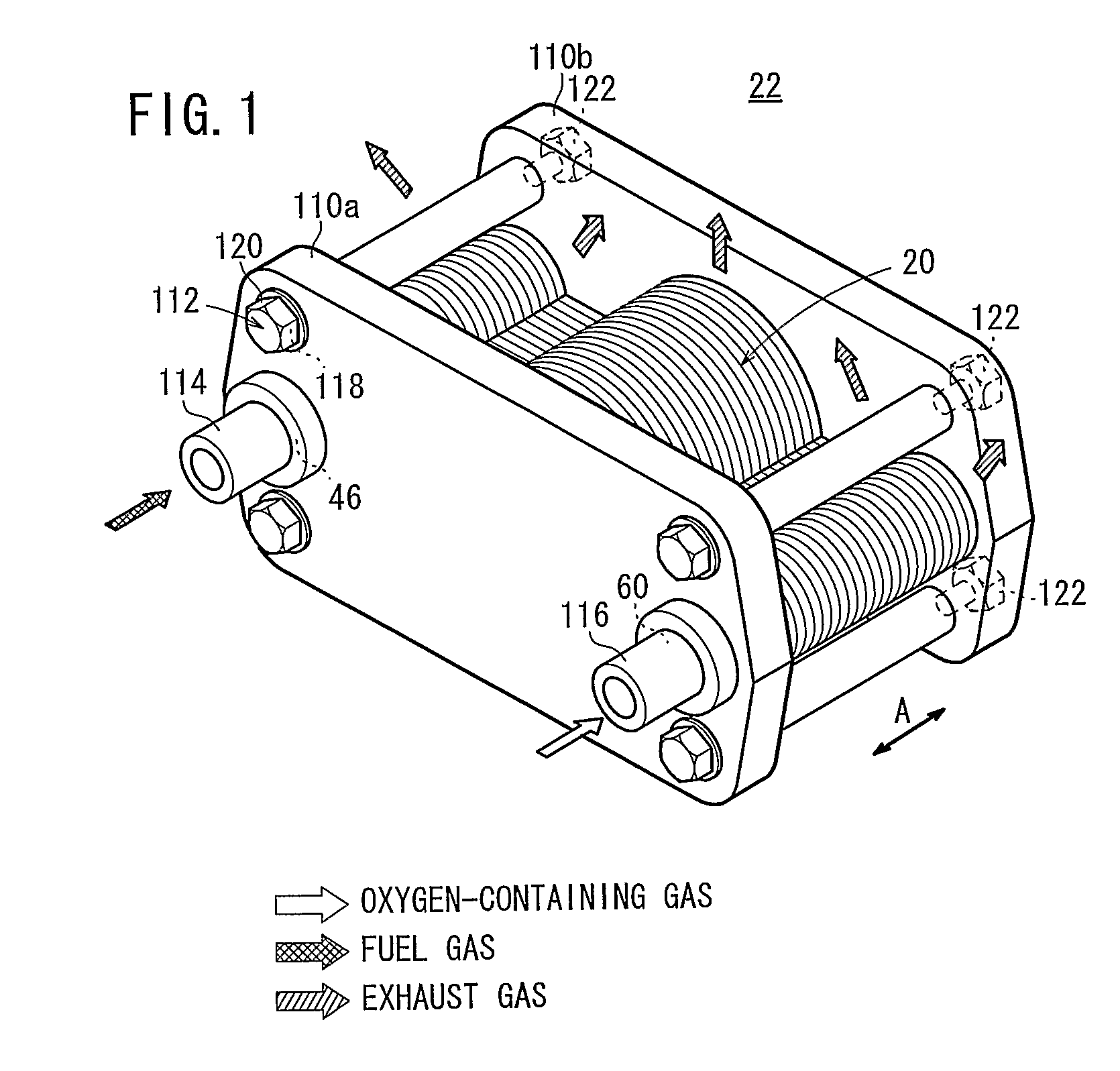
[0049]FIG. 1 is a perspective view schematically showing a fuel cell stack 22 formed by stacking a plurality of fuel cells 20 according to the present invention in a direction indicated by an arrow A.

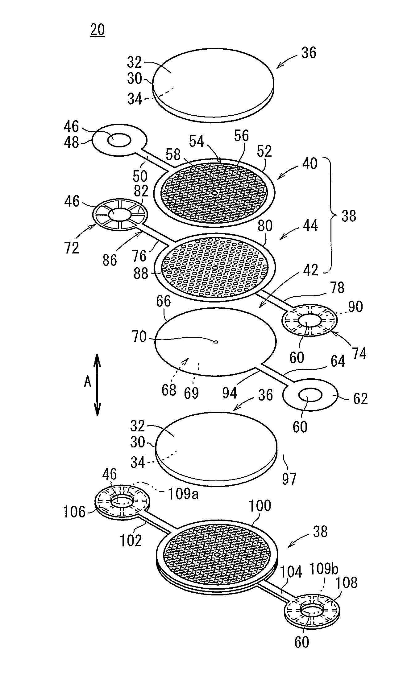
[0050]The fuel cell 20 is a solid oxide fuel cell (SOFC) used in various applications, including stationary and mobile applications. For example, the fuel cell 20 is mounted on a vehicle. As shown in FIGS. 2 and 3, the fuel cell 20 includes an electrolyte electrode assembly 36. The electrolyte electrode assembly 36 includes a cathode 32, an anode 34, and an electrolyte (electrolyte plate) 30 interposed between the cathode 32 and the anode 34. For example, the electrolyte 30 is made of ion-conductive solid oxide such as stabilized zirconia. The electrolyte electrode assembly 36 has a circular disk shape.

[0051]The fuel cell 20 is formed by sandwiching a single electrolyte electrode assembly 36 between a pair of separators 38 according to the first embodiment. The separator 38 includes fir...

fourth embodiment

[0124]FIG. 18 is an exploded perspective view showing a fuel cell 270 according to the present invention.

[0125]The fuel cell 270 includes a plurality of, e.g., four electrolyte electrode assemblies 36 and a pair of separators 272 sandwiching the electrolyte electrode assemblies 36. Each of the separators 272 includes a first plate 274 and a second plate 276. For example, the first and second plates 274, 276 are metal plates of, e.g., stainless alloy.

[0126]A first fuel gas supply section 278 is formed at the center of the first plate 274, and the fuel gas supply passage 46 extends through the first fuel gas supply section 278. Four first bridges 280 extend radially outwardly from the first fuel gas supply section 278 at equal intervals. The first fuel gas supply section 278 is integral with first sandwiching sections 282 each having a relatively large diameter through the first bridges 280. The first sandwiching section 282 and the electrolyte electrode assembly 36 have substantially...

fifth embodiment

[0140]FIG. 21 is an exploded perspective view showing a fuel cell 310 according to the present invention.

[0141]The fuel cell 310 is formed by sandwiching a plurality of, e.g., four electrolyte electrode assemblies 36 between a pair of separators 312. A first fuel gas supply section 314 is formed at the center of the separator 312, and the fuel gas supply passage 46 extends through the first fuel gas supply section 314. Four first bridges 316 extend radially outwardly from the first fuel gas supply section 314 at equal intervals. The first bridges 316 are integral with first sandwiching sections 318 each having a circular disk shape.

[0142]The centers of the sandwiching sections 318 are equally distanced from the center of the first fuel gas supply section 314. The sandwiching sections 318 are separated from each other. A plurality of first projections 56 forming the fuel gas channel 54 are provided on a surface 318a of the sandwiching section 318 which contacts the anode 34.

[0143]A f...


PUM


Abstract

A separator of a fuel cell includes a sandwiching section, first and second bridges connected to the sandwiching section, a fuel gas supply section connected to the first bridge and an oxygen-containing gas supply section connected to the second bridge. The sandwiching section sandwiches an electrolyte electrode assembly, and has a fuel gas channel and an oxygen-containing gas channel separately. In the sandwiching section, a plurality of first projections are arranged in a zigzag pattern in a direction in which the first bridge extends, and the first projections at least protrude toward the fuel gas channel to contact an anode.

Description

TECHNICAL FIELD[0001]The present invention relates to a fuel cell formed by stacking electrolyte electrode assemblies and separators alternately. Each of the electrolyte electrode assembles includes an anode, a cathode, and an electrolyte interposed between the anode and the cathode.BACKGROUND ART[0002]Typically, solid oxide fuel cells (SOFC) employ an electrolyte of ion-conductive solid oxide such as stabilized zirconia. The electrolyte is interposed between an anode and a cathode to form an electrolyte electrode assembly (MEA). The electrolyte electrode assembly is interposed between a pair of separators (bipolar plates). In use, generally, a predetermined number of the separators and the electrolyte electrode assemblies are stacked together to form a fuel cell stack.[0003]As the structure of the fuel cell of this type, for example, the fuel cell separator structure disclosed in Japanese Laid-Open Patent Publication No. 63-266777 is known. In the separator structure, a corrugated ...

Claims


Application Information

Patent Timeline
IPC IPC(8): H01M8/04H01M8/24
CPCH01M8/0254H01M8/0258Y02E60/525H01M2008/1293Y02E60/50H01M8/2425H01M8/2432H01M8/2457H01M8/2483H01M8/2484H01M8/241
Inventor HOMMA, HIROKITAKAHASHI, TSUTOMUOGAWA, TETSUYA
Owner HONDA MOTOR CO LTD
Why Eureka
Try Eureka