
Seat device for vehicle

Inactive Publication Date: 2011-03-31
MAZDA MOTOR CORP
View PDF3 Cites 92 Cited by
  • Summary
  • Abstract
  • Description
  • Claims
  • Application Information

AI Technical Summary

Benefits of technology

[0005]The present invention has been devised in view of the above-described problem, and an object of the present invention is to provide a seat device for a vehicle which can protect the driver's head properly with a simple structure, without utilizing the above-described rear parcel trim and the like.
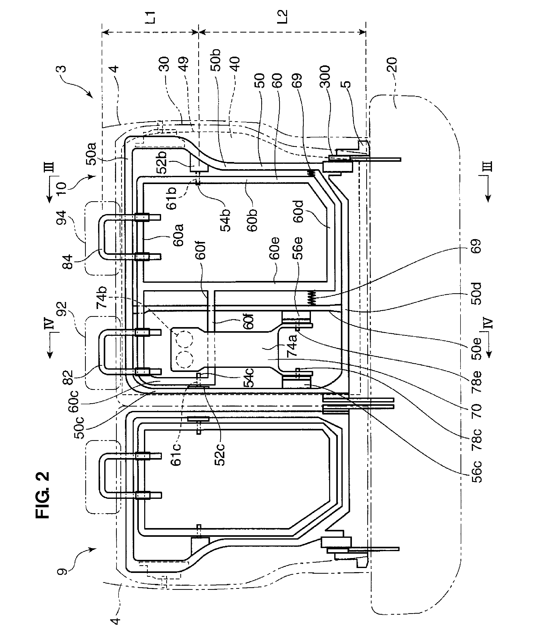
[0007]According to the present invention, since the headrest is moved forwardly or upwardly at the vehicle rear collision, the rearward move of the passenger's head can be suppressed. Further, since the pressure-receiving portion is provided at the second portion of the seatback which is arranged beside the first portion of the seatback, the headrest provided at the upper portion of the first portion of the seatback can be moved even in case it is difficult to arrange the pressure-receiving portion at the first portion of the seatback, so that the head of the passenger seated in front of the first portion can be protected securely. In case it is possible to arrange the pressure-receiving portion at the first portion, meanwhile, the headrest can be moved by the rearward move of the passenger seated in front of the second portion in addition to the passenger seated in front of the first portion, so that the move of the headrest can be properly secured.
[0012]According to the above-described embodiment, it can be prevented that the above-described connection portion of the headrest moving mechanism interferes with the above-described small-article storage portion when the connection portion swings longitudinally. Thus, the forward or upward move of the headrest can be achieved, providing the small-article storage portion at the armrest. Further, since there is no need of providing a large longitudinal distance between the connection portion and the small-article storage portion for avoiding the above-described interference, the thickness of the seatback where the connection portion is arranged can be kept properly thin.
[0013]According to another embodiment of the present invention, the connection portion of the headrest moving mechanism comprises an upper swing portion which extends in a seat width direction and is connected to the headrest, a lateral swing portion which extends downward from an end of the upper swing portion in the seat width direction and to which the swing axis is attached, and a middle swing portion which extends from the lateral swing portion in the seat width direction substantially at the same height position as the swing axis, the upper swing portion being arranged at a specified position so as not to interfere with the small-article storage portion when swinging longitudinally around the swing axis, the middle swing portion being arranged at a specified position which is located between the small-article storage portion and the support axis of the armrest located in the storage position and rearwardly from a part of the armrest between the small-article storage portion and support axis. Thereby, the headrest is supported at the respective swing portions stably, so that the stable forward or upward move of the headrest in accordance with the swing of the respective swing portions can be achieved. Further, since the middle swing portion is arranged in back of the armrest, the armrest can be rotated without being hindered by the middle swing portion. Moreover, since the middle swing portion is arranged at the same height position as the swing axis, the longitudinal swinging amount of the middle swing portion can be made as small as possible, so that any interference of the middle swing portion with the armrest can be avoided securely.
[0014]According to another embodiment of the present invention, the seat device for a vehicle further comprises a second headrest provided at an upper portion of the second portion of the seatback to support a head of the passenger seated in front of the second portion of the seatback, wherein the headrest moving mechanism connects the pressure-receiving portion to the second headrest provided at the upper portion of the second portion of the seatback so that the second headrest is moved forwardly or upwardly in accordance with the rearward move of the pressure-receiving portion. Thereby, both the first portion and the second portion of the seatback can be moved forwardly or upwardly concurrently in accordance with the rearward move of the pressure-receiving portion at the vehicle rear collision, and the structure can be properly simple without providing any particular mechanism for moving the headrest.

Problems solved by technology

Therefore, in case the rear parcel trim and the like are not arranged in back of the seatback, this seat device may not be applicable to such a vehicle.

Method used


Image

  • Seat device for vehicle
  • Seat device for vehicle
  • Seat device for vehicle

Examples


Embodiment Construction

[0022]Hereinafter, preferred embodiments of the present invention will be described referring to the accompanying drawings.

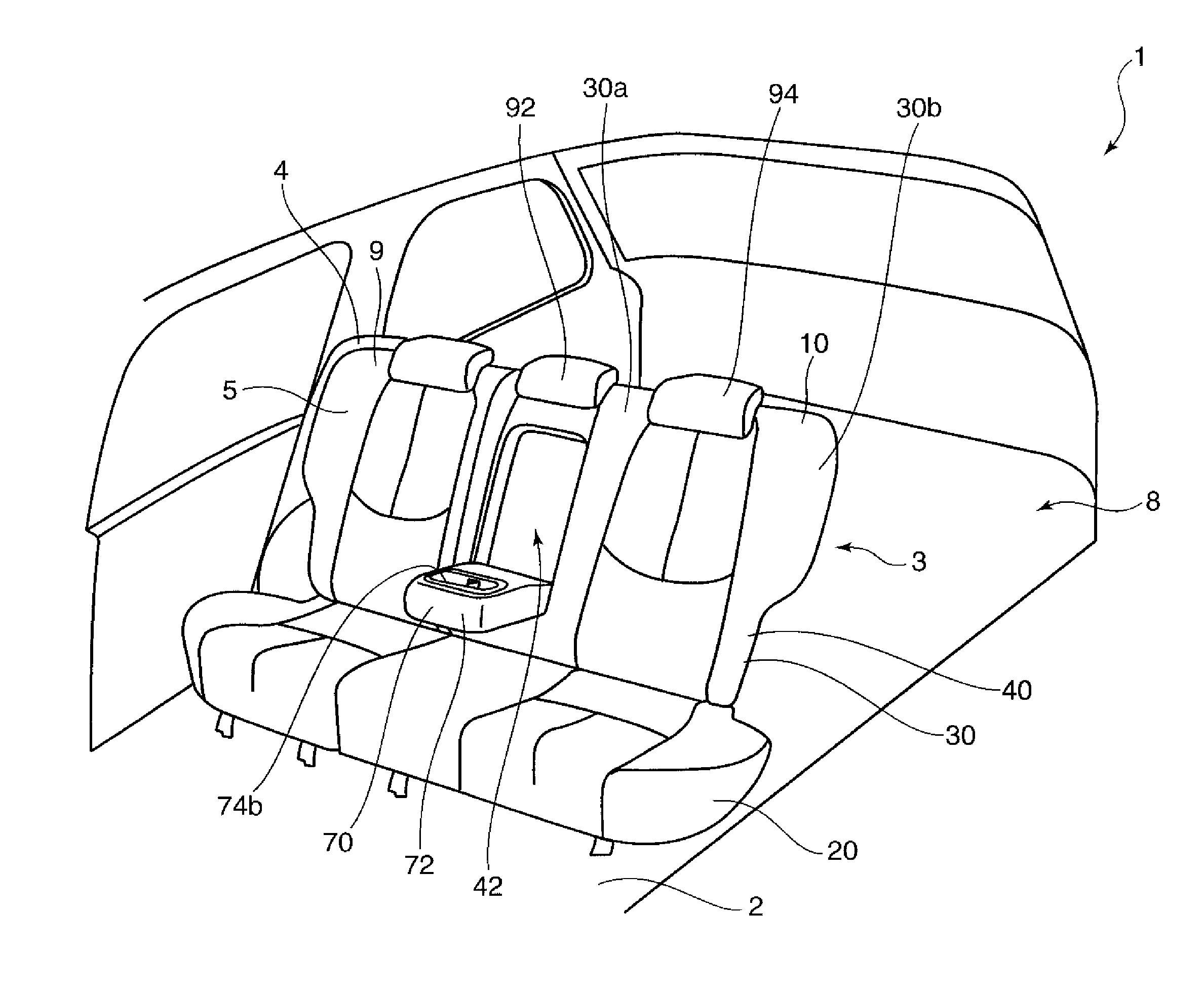
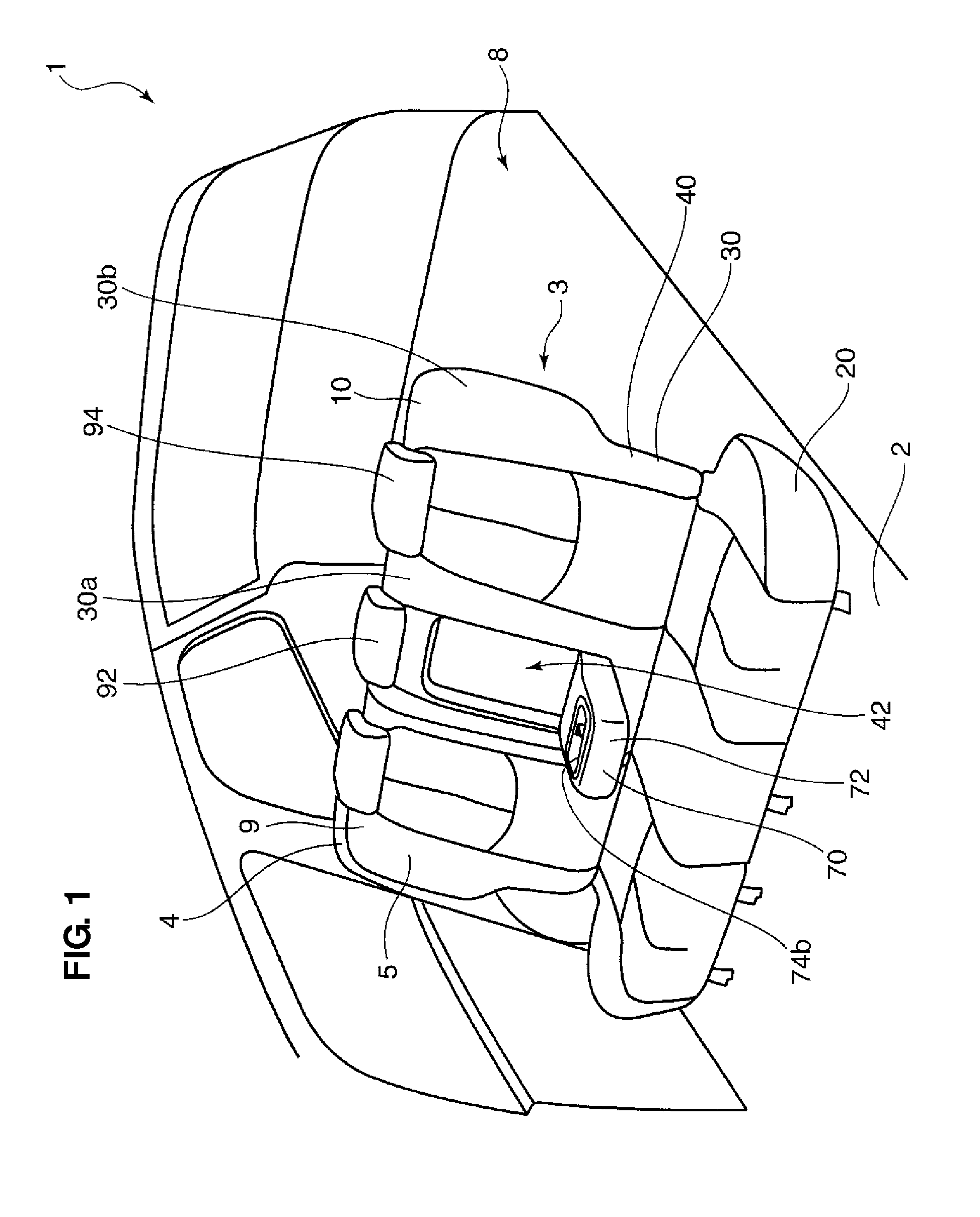
[0023]FIG. 1 is a schematic perspective view showing a rear part of a vehicle 1 which is equipped with a seat device for a vehicle according to the present invention. In a rear part of the vehicle 1 behind a driver's seat and a passenger's (assistant's) seat, which are not illustrated, a rear seat 3 is disposed on a floor panel 2 which forms a bottom of a vehicle compartment. The rear seat 3 is configured to be available for sitting of three passengers. This rear seat 3 comprises a seat for a single passenger 9 and a bench type of seat for two passengers 10, which are arranged side by side in a vehicle width direction. Herein, an example in which the bench type of seat 10 performs as the above-described seat device for a vehicle will be described. Vehicle-body frames 4, 4 are provided at both sides of the rear seat 3 in the vehicle width direction. A baggage com...


PUM


Abstract

There are provided a seatback supporting backs of plural passengers seated on a bench type of seat cushion, a headrest provided at an upper portion of a first portion of the seatback and supporting a head of the passenger seated in front of the first portion, a pressure-receiving portion provided at a second portion of the seatback which is arranged beside the first portion so as to move rearwardly when being pressed by a rearward move of the passenger seated in front of the second portion, and a headrest moving mechanism provided to connect the pressure-receiving portion to the headrest so that the headrest is moved forwardly or upwardly in accordance with a rearward move of the pressure-receiving portion. Accordingly, the passenger's head can be protected with a simple structure.

Description

BACKGROUND OF THE INVENTION[0001]The present invention relates to a seat device for a vehicle.[0002]Conventionally, a vehicle, such as an automotive vehicle, in which a headrest which is provided at a seat to support a head of a passenger is moved forwardly at a vehicle rear collision in order to suppress a rearward move of the passenger's head for protection of the passenger's head, has been developed.[0003]Japanese Patent Laid-Open Publication No. 2008-273445, for example, discloses a seat device, in which a rear parcel shelf is disposed in back of a seatback supporting a back of a passenger, a headrest support portion which projects forwardly from a front face of the rear parcel shelf is provided at a rear parcel trim which covers over the rear parcel shelf, and the seatback is supported at the rear parcel shelf via a spring provided between the rear parcel shelf and the seatback. In this seat device, when the vehicle has a rear collision, the rearward move of the headrest is sup...

Claims


Application Information

Patent Timeline
IPC IPC(8): A47C1/031B60N2/75
CPCB60N2/4228B60N2/4885B60N2/4835B60N2/4686B60N2/793B60N2/835B60N2/888
Inventor NAKAYA, KOUICHIKOBAYASHI, AKIHIRO
Owner MAZDA MOTOR CORP
Learn More