
Rechargeable electrochemical cell system with a charging electrode charge/discharge mode switching in the cells

Inactive Publication Date: 2011-03-24
FLUIDIC
View PDF99 Cites 219 Cited by
  • Summary
  • Abstract
  • Description
  • Claims
  • Application Information

AI Technical Summary

Benefits of technology

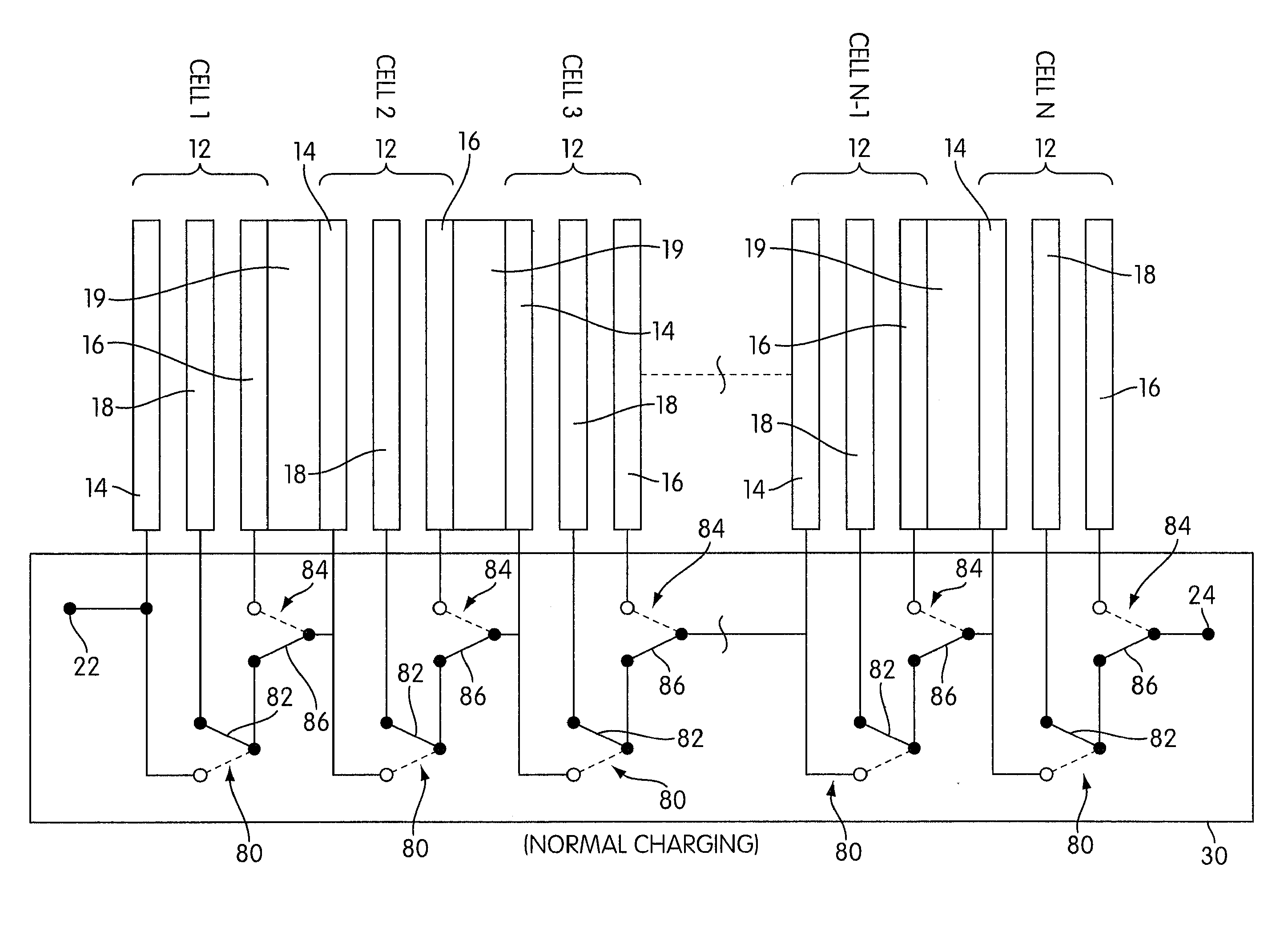
[0008](2) a charge mode coupling the charging electrode of each cell 1 to N−1 to the fuel electrode of the subsequent cell to couple the cells in a charging series, such that when the fuel electrode of cell 1 and the charging electrode of cell N are coupled to a power source to receive a charging potential difference cathodic at the fuel electrode of cell 1 and anodic at the charging electrode of cell N, an incremental potential difference is created within each cell to reduce a reducible fuel species at the fuel electrode and oxidize an oxidizable oxidant species at the charging electrode.

Problems solved by technology

These terminals connect to a load, creating a potential difference that drives current.

Method used


Image

  • Rechargeable electrochemical cell system with a charging electrode charge/discharge mode switching in the cells
  • Rechargeable electrochemical cell system with a charging electrode charge/discharge mode switching in the cells
  • Rechargeable electrochemical cell system with a charging electrode charge/discharge mode switching in the cells

Examples


Embodiment Construction

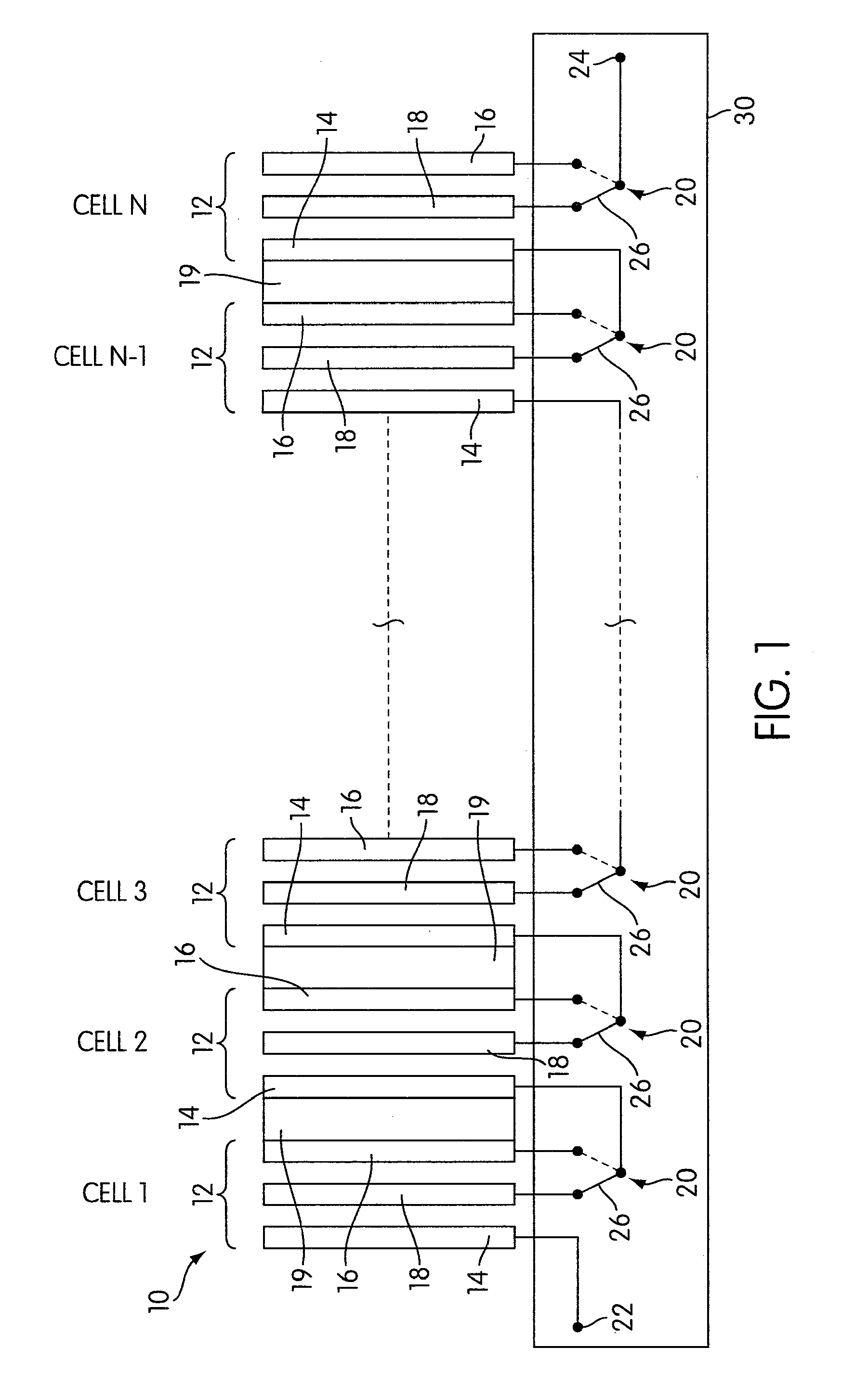
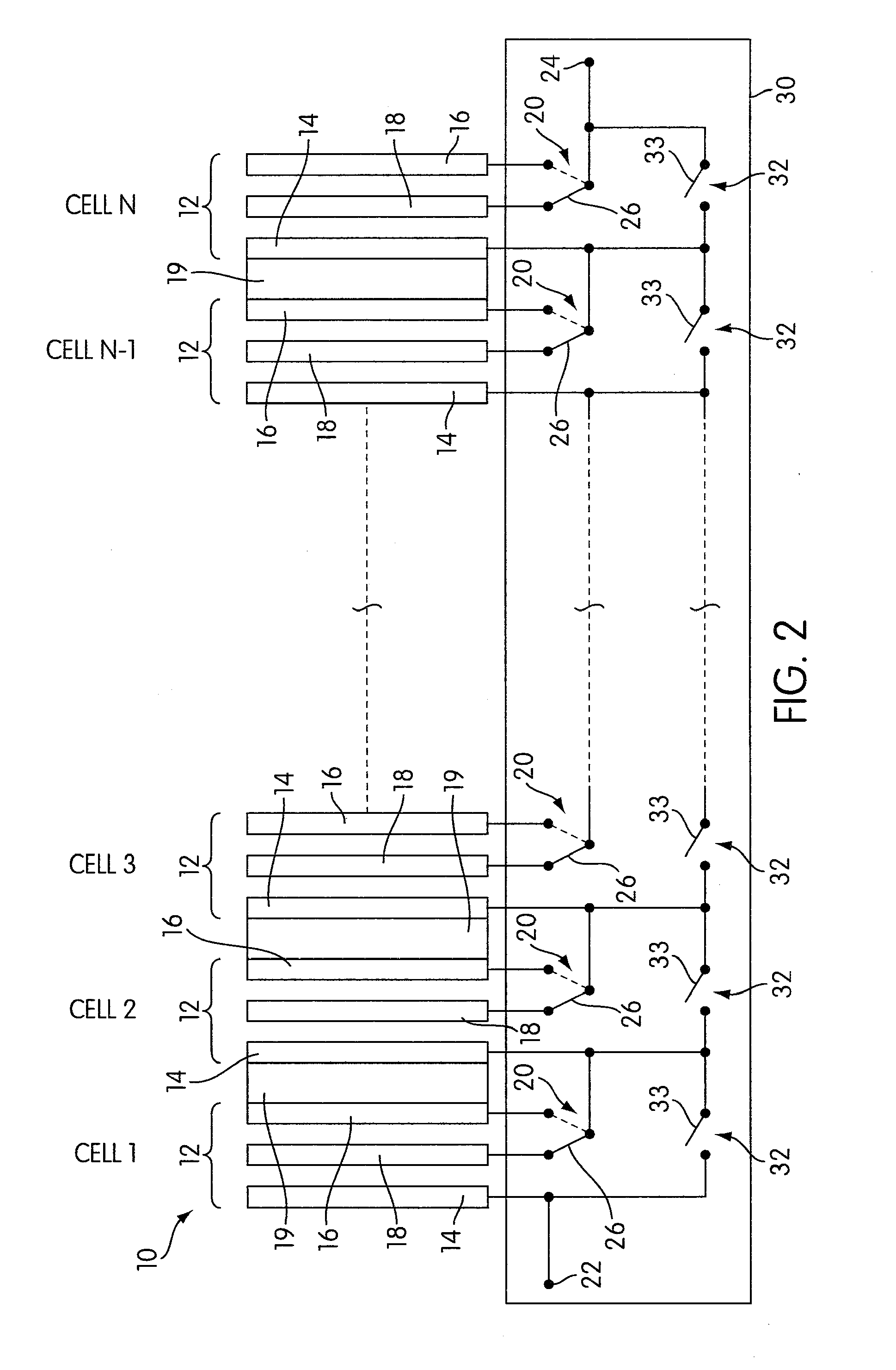
[0030]The Figures illustrate various embodiments of a rechargeable electrochemical cell system 10 for generating electrical current using a fuel and an oxidant. The cell system 10 may have any arrangement and architecture, and the illustrated embodiments are not intended to be limiting.

[0031]The cell system 10 comprises N electrochemical cells 12. The number N is any integer greater than or equal to two, and is not limited to any particular number. Each cell 12 comprises a fuel electrode 14, an oxidant electrode 16, a charging electrode 18, and an ionically conductive medium communicating the electrodes 14, 16, 18. Each cell 12 is preferably encased to prevent leakage of the ionically conductive medium, which may be an electrolyte or any suitable medium for enabling ion transport during charging / discharging. For example, a conventional liquid or semi-solid electrolyte solution may be used, or a room temperature ionic liquid may be used, as mentioned in U.S. Patent Appln. No. 61 / 177,...


PUM


Abstract

One aspect of the present invention provides a rechargeable electrochemical cell system for generating electrical current using a fuel and an oxidant. The cell system comprises N electrochemical cells each comprising a fuel electrode, an oxidant electrode, a charging electrode, and an ionically conductive medium communicating the electrodes, wherein N is an integer greater than or equal to two. Any number of cells may be used. The cell system includes a plurality of switches that are switcheable to a discharge mode coupling the oxidant electrode of each cell to the fuel electrode of the subsequent cell, a charge mode coupling the charging electrode of each cell to the fuel electrode of the subsequent cell, and a bypass mode coupling charging electrode or the oxidant electrode of a previous cell to the fuel electrode of a subsequent cell.

Description

CROSS-REFERENCE TO RELATED APPLICATIONS[0001]The present application claims the benefit of priority from U.S. Provisional Patent Application No. 61 / 243,970, filed on Sep. 18, 2009, the content of which is incorporated herein by reference in its entirety.FIELD OF THE INVENTION[0002]The present invention relates to a rechargeable electrochemical cell system comprising a plurality of cells that each includes a charging electrode in addition to the fuel and oxidant electrodes.BACKGROUND OF THE INVENTION[0003]Electrochemical cell systems with a plurality of individual electrochemical cells connected in series are well known. Each individual cell includes an anode or fuel electrode at which a fuel oxidation reaction takes place, a cathode or oxidant electrode at which an oxidant reduction reaction takes place, and an ionically conductive medium for supporting the transport of ions. The fuel electrode of the first cell is coupled to a first terminal, the oxidant electrode of each cell with...

Claims


Application Information

Patent Timeline
IPC IPC(8): H01M12/06H01M8/04
CPCY02E60/528H01M8/04873H01M12/08H01M8/24H01M8/184H01M8/0271Y02E60/10
Inventor FRIESEN, CODY A.KRISHNAN, RAMKUMARFRIESEN, GRANT
Owner FLUIDIC
Learn More