
Image pickup apparatus and control method and program of the same

a technology of image pickup and control method, which is applied in the direction of color television details, television systems, climate sustainability, etc., can solve the problems of inability to synchronize the camera and the flash device, the standby electricity consumption is larger than that in the case of using the sleep state, and the timing of the camera and the camera accessory can communicate limited, so as to achieve the effect of efficient suppression of standby electricity consumption

Inactive Publication Date: 2011-03-17
CANON KK
View PDF5 Cites 17 Cited by
  • Summary
  • Abstract
  • Description
  • Claims
  • Application Information

AI Technical Summary

Benefits of technology

[0011]In order to solve the above-described problems, it is an aspect of the invention to provide an image pickup apparatus for wireless-communicating with another apparatus, in which while efficiently suppressing stand-by electricity consumption, a delay of timing at which a predetermined processing is executed between apparatuses can be avoided.
[0014]According to the image pickup apparatus and the accessory apparatus of the present invention, while suppressing stand-by electricity consumption as much as possible, another apparatus can execute a predetermined processing at an exact timing thereof.

Problems solved by technology

However, by using the sleep state, timing when the camera and the camera accessory can communicate is limited.
Therefore, there is a case where timing at which the flash device emits light is delayed, so that there may be a possibility that a synchronization between the camera and the flash device becomes impossible.
However, if the flash device is set into the communication always-active state in order to perform the synchronization, the stand-by electricity consumption becomes larger than that in the case of using the sleep state.
However, the method proposed in the Official Gazette of Japanese Patent Application Laid-Open No. 2006-314093 is the control method for minimizing the electricity consumption of the information processing apparatus and does not eliminate a delay of timing at which a predetermined processing is executed between the information processing apparatuses.

Method used


Image

  • Image pickup apparatus and control method and program of the same
  • Image pickup apparatus and control method and program of the same
  • Image pickup apparatus and control method and program of the same

Examples


first embodiment

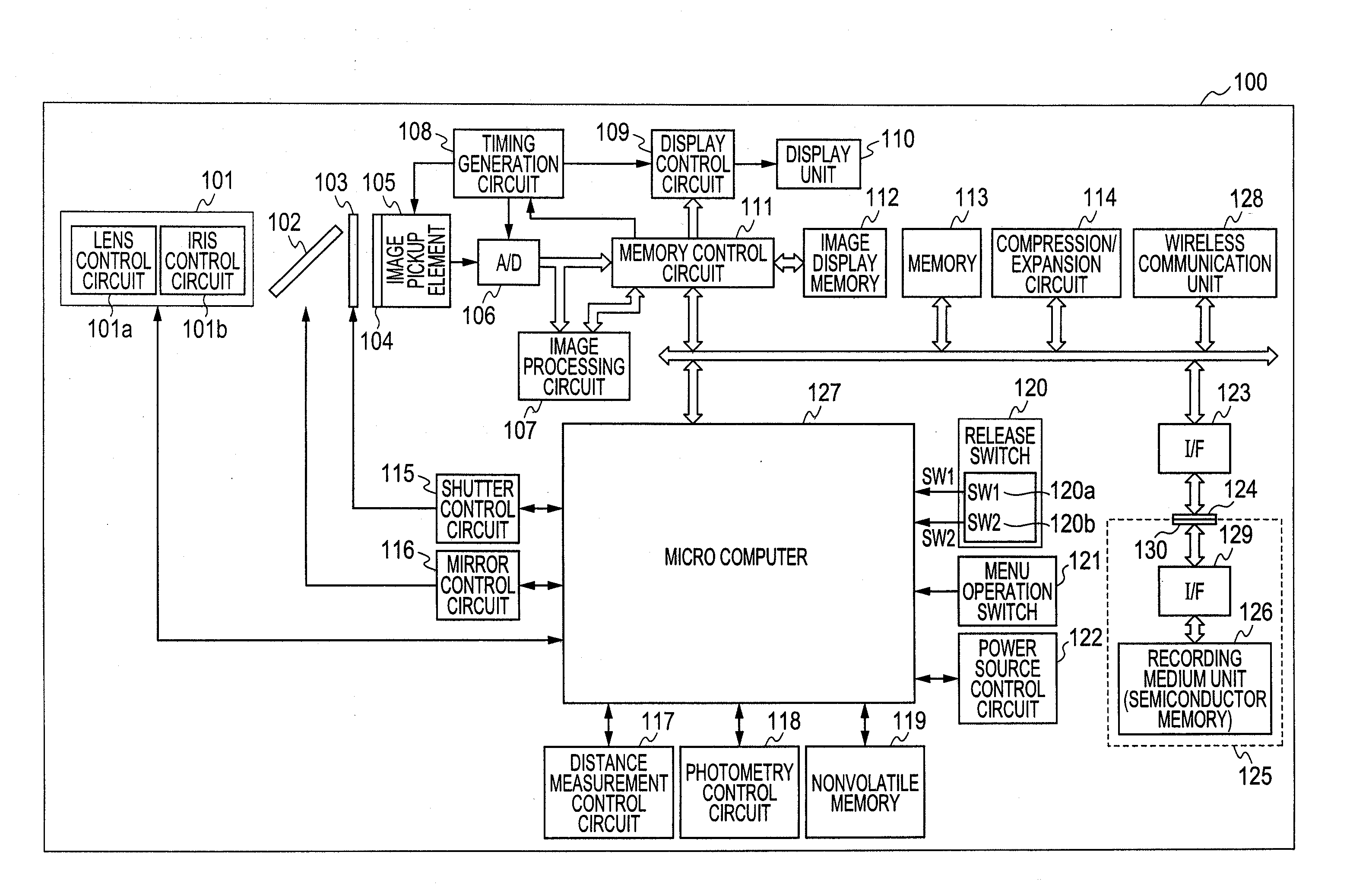
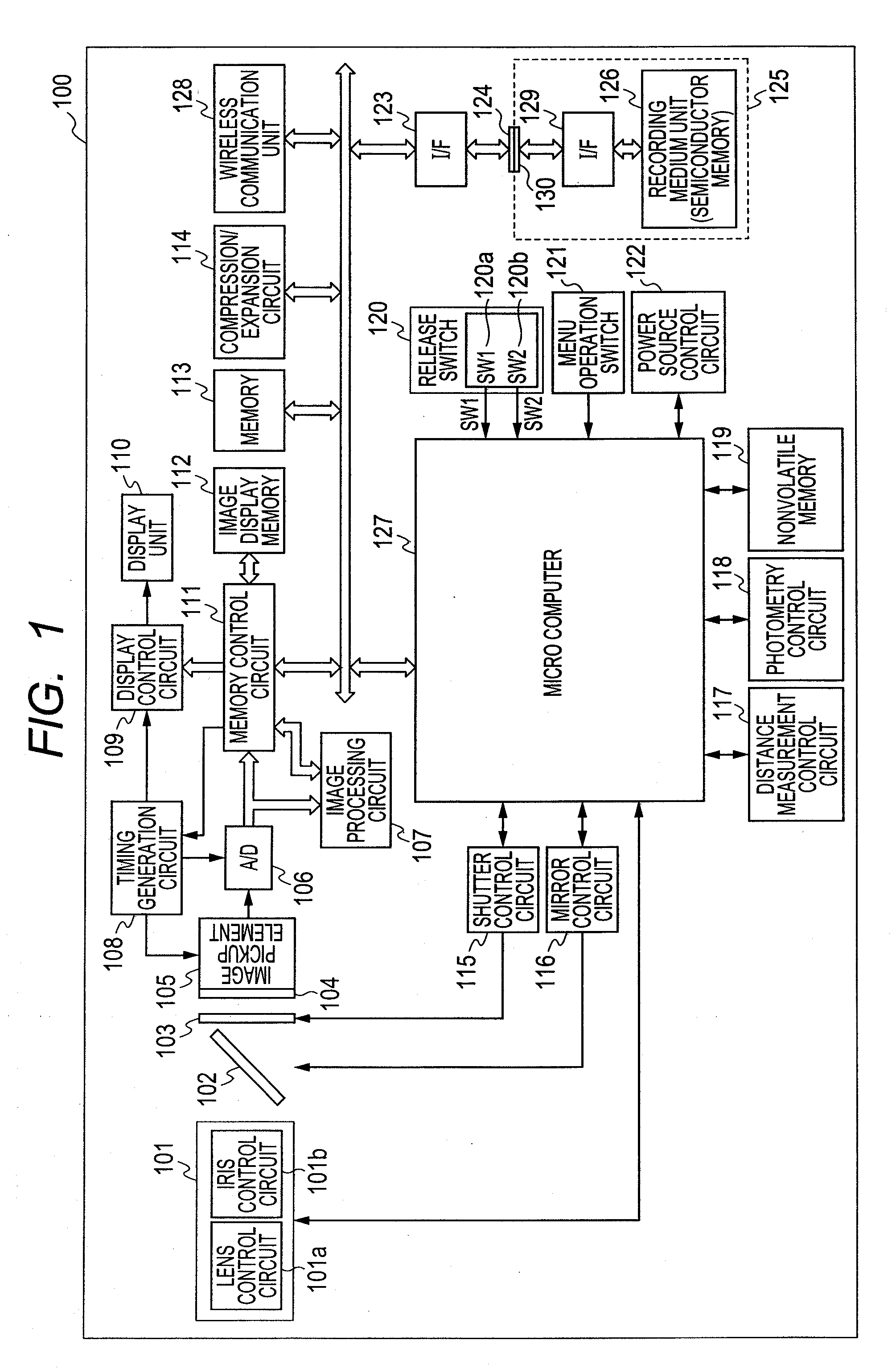
[0027]FIG. 1 is a schematic diagram illustrating an example of a construction of a digital still camera (hereinbelow, referred to as a camera) serving as an image pickup apparatus according to the first embodiment of the invention. In FIG. 1, a camera 100 in the embodiment is illustrated.

[0028]In the camera 100, an interchangeable photographing lens unit 101 is constructed by a plurality of lens groups. The photographing lens unit 101 communicates with a microcomputer 127 and performs an auto-focus (AF) by a lens control circuit 101a in the photographing lens unit 101. In more detail, a focal point is in-focused by moving a focusing lens in the photographing lens unit 101 by control of the lens control circuit 101a. A movement amount is arithmetically operated by the microcomputer 127 based on an output of a distance measurement control circuit 117. An iris control circuit 101b is provided in the photographing lens unit 101. The iris control circuit 101b changes an optical iris valu...

second embodiment

[0063]Subsequently, the second embodiment of the invention will be described. FIG. 6 is a diagram illustrating a construction of a camera system in the second embodiment. In FIG. 6, the camera system is constructed by the camera 100 and two flash devices 600 and 601. A construction of the camera 100 is similar to the construction described in the first embodiment. A construction of each of the flash devices 600 and 601 is also similar to the construction described in the first embodiment. The flash devices 600 and 601 have wireless communication units 602 and 603 in order to communicate with the wireless communication unit 128 held in the camera 100, respectively. Each of the wireless communication units 602 and 603 is similar to that of the flash device 200 described in the first embodiment.

[0064]In the case where there are a plurality of flash devices as in the embodiment, there may exist a flash device as a non-control object which does not need to be operated in accordance with ...

third embodiment

[0076]Subsequently, the third embodiment of the invention will be described. A construction of a camera system in the embodiment is similar to that in FIG. 6 illustrated in the second embodiment. In the third embodiment, a case where the flash devices 600 and 601 are selected as control objects by the menu operation switch 121 when the flash devices 600 and 601 are the non-control objects (S704) will now be described. At this time, as for the flash devices 600 and 601, if the synchronization timing when the wireless communication path between the flash device 600 and the camera 100 has been established and that between the flash device 601 and the camera 100 differ, the timing for synchronizing with the camera 100 also differ. Therefore, in the case of selecting both of the flash devices 600 and 601 as control objects, it is necessary to match the synchronization timing when the control objects are selected. In the embodiment, the operation for changing the sleep periods of the flas...


PUM


Abstract

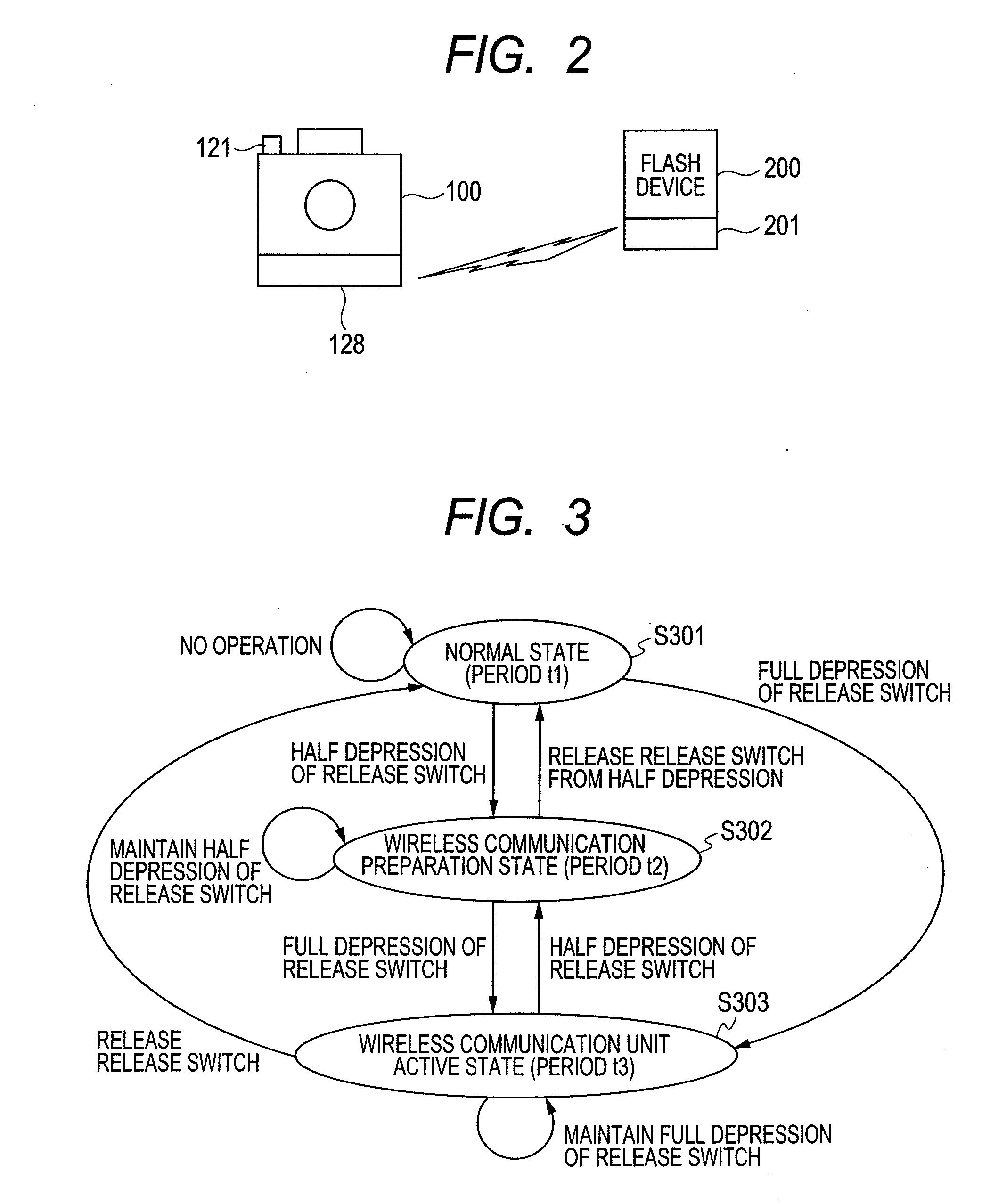
An image pickup apparatus for wireless-communicating with a camera accessory which periodically transits to a sleep state, transmits a change signal for changing the setting of a power saving state in an accessory apparatus, to the accessory apparatus in accordance with a first operation for instructing an image pickup preparation to decide an setting for image pickup or a second operation for instructing the image pickup based on the image pickup preparation operation being accepted by an operation unit of the image pickup apparatus, thereby efficiently suppressing stand-by electricity consumption and preventing a delay from occurring in timing when a predetermined process is executed between apparatuses.

Description

BACKGROUND OF THE INVENTION[0001]1. Field of the Invention[0002]The present invention relates to an image pickup apparatus which can wireless-communicate with another apparatus.[0003]2. Description of the Related Art[0004]In recent years, a wireless communicating apparatus is installed into a digital still camera (hereinbelow, referred to as a camera), so that the camera and a camera accessory wireless-communicate with each other, thereby enabling them to mutually control. At the time of the wireless communication, a communication module of the camera or camera accessory which is driven is made to periodically transit to a sleep state, thereby suppressing stand-by electricity consumption to a value smaller than that in a communication always-active state.[0005]However, by using the sleep state, timing when the camera and the camera accessory can communicate is limited. Therefore, if a transmission side transmitted a command to a reception side in the sleep state, the reception side ...

Claims


Application Information

Patent Timeline
Patent Type & Authority Applications(United States)
IPC IPC(8): H04N5/232
CPCH04N5/2256H04N5/23212Y02B60/50H04N5/2354H04N5/2353H04N23/56H04N23/661H04N23/67H04N23/651H04N23/73H04N23/74
Inventor KOIKE, KOUTAROU
Owner CANON KK
Learn More