
Solar energy power generation system

a solar energy and power generation system technology, applied in the field of power generation, can solve the problems of large installation area, high cost, and inability to efficiently and cost effectively convert solar energy to electricity, and achieve the effect of maximizing solar energy collected

Active Publication Date: 2011-03-17
SOLAR LOGIC
View PDF29 Cites 16 Cited by
  • Summary
  • Abstract
  • Description
  • Claims
  • Application Information

AI Technical Summary

Benefits of technology

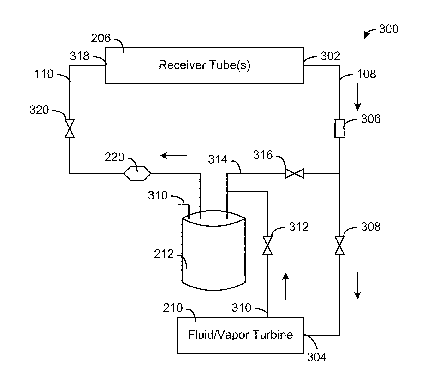
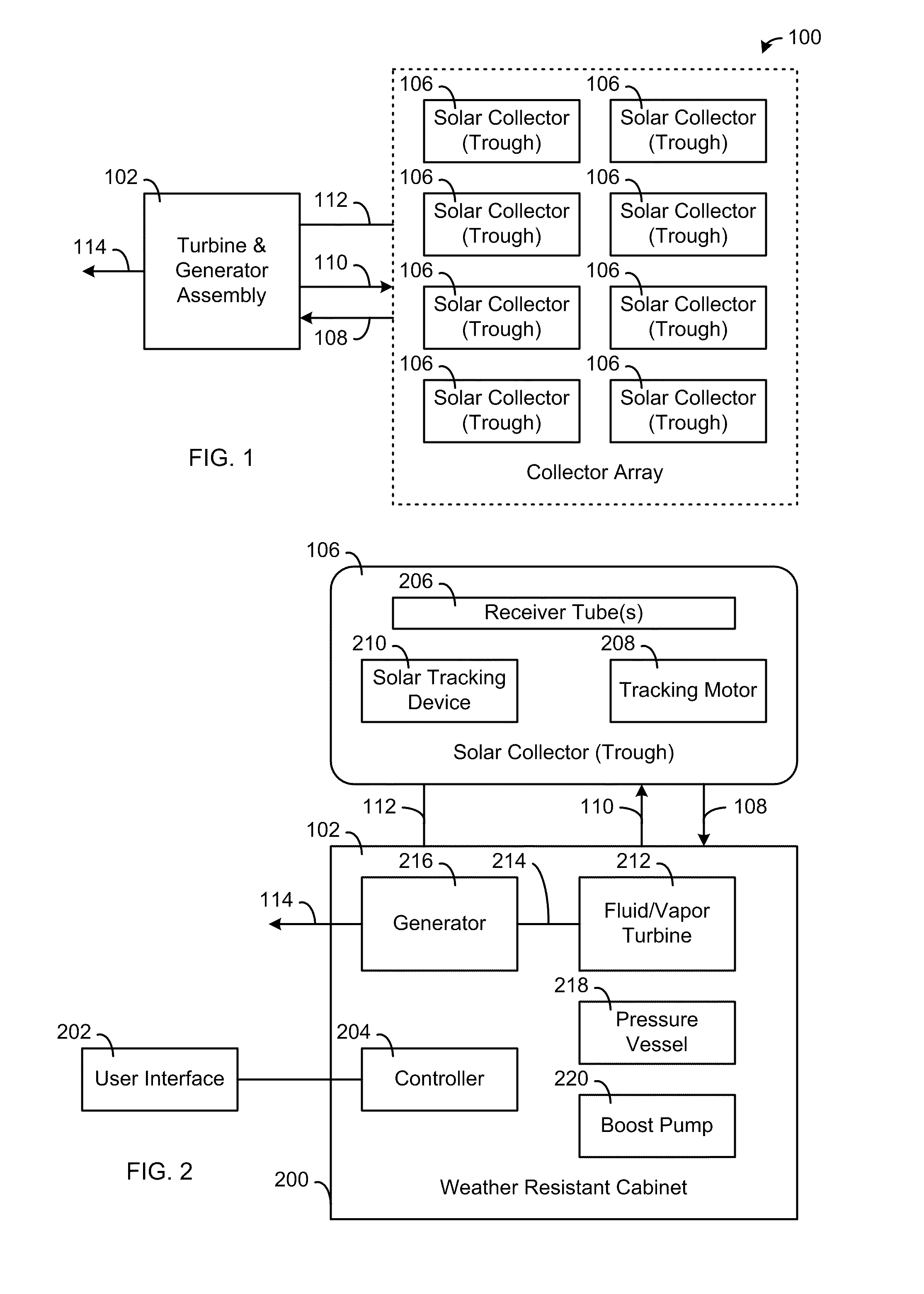
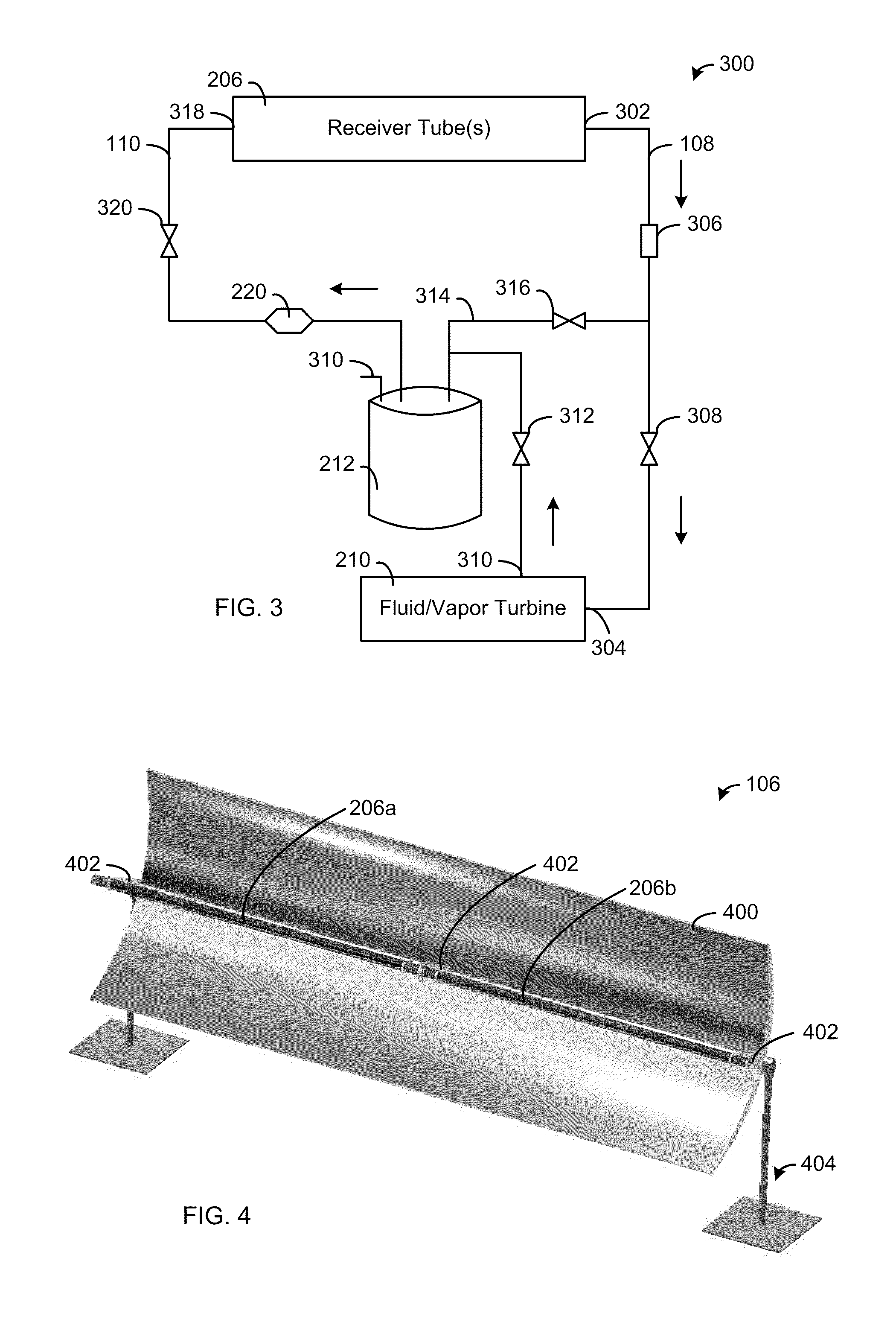
[0006]More specifically, the present invention provides a solar power system that includes one or more solar collectors, a solar tracking device, a fluid/vapor turbine, a generator and a controller. Each solar collector includes (a) one or more support structures for securely mounting the solar collector to a surface, (b) a reflective parabolic trough for concentrating solar energy along a focal axis and attached to the support structure(s) to allow rotation of the reflective parabolic trough around a longitudinal axis, (c) one or more receiver tubes attached to the reflective parabolic trough along the focal axis, and (d) a motor operably connected to the reflective parabolic trough to rotate the reflective parabolic trough around the longitudinal axis. Each receiver tube includes (i) a metal tube having an inlet, an outlet and a solar absorption coating, and (ii) a transparent tube having a first seal and a second seal to vacuum or hermetically seal the metal tube between approximately the inlet and the outlet within the transparent tube. The solar tracking device has one or more sensors to control the motor to align each solar collector to maximize the solar energy collected by the one or more receiver tubes. The fluid/vapor turbine has a drive shaft, a fluid/vapor inlet connected to the outlet of the receiver tube(s) and a fluid/vapor outlet connected to the inlet of the receiver tube(s). The generator is connected to the drive shaft of the fluid/vapor turbine and having one or more electrical output terminals. The controller is connected to the motor, the solar tracking device, the fluid/vapor turbine and the generator to monitor and control the system.
[0007]In addition, the present invention provides a solar power system that includes one or more solar collectors, a solar tracking device, a fluid/vapor turbine, a generator and a controller. Each solar collector includes (a) one or more support structures for securely mounting the solar collector to a surface, (b) a reflective parabolic trough for concentrating solar energy along a focal axis and attached to the support structure(s) to allow rotation of the reflective parabolic trough around a longitudinal axis, (c) one or more receiver tubes attached to the reflective parabolic trough along the focal axi...

Problems solved by technology

But, these existing solar energy systems typically have low thermal efficiencies, require large installation areas and / or require expensive components.
As a result, systems to efficiently and cost effectively convert solar energy to electricity are not available to the general public.

Method used


Image

  • Solar energy power generation system
  • Solar energy power generation system
  • Solar energy power generation system

Examples


Embodiment Construction

[0020]While the making and using of various embodiments of the present invention are discussed in detail below, it should be appreciated that the present invention provides many applicable inventive concepts that can be embodied in a wide variety of specific contexts. The specific embodiments discussed herein are merely illustrative of specific ways to make and use the invention and do not delimit the scope of the invention. The discussion herein relates primarily to reflective parabolic trough solar collectors, but it will be understood that the concepts of the present invention are applicable to any type of solar collector, such as a parabolic dish.

[0021]The present invention provides a system for generating AC electrical power from solar radiation through the use of parabolic troughs capturing the energy and a fluid turbine to convert the solar energy to mechanical energy. The turbine is directly coupled to a generator to produce AC electrical power.

[0022]Now referring to FIG. 1,...


PUM


Abstract

A solar energy power generation system generates AC electrical power from solar radiation through the use of parabolic troughs to capture the energy and a fluid turbine to convert the solar energy to mechanical energy. The turbine is directly coupled to a generator to produce AC electrical power.

Description

CROSS-REFERENCE TO RELATED APPLICATIONS[0001]This patent application is a non-provisional application of U.S. patent application 61 / 243,154 filed on Sep. 16, 2009 entitled “Solar Energy Power Generation System”, which is hereby incorporated by reference in its entirety. This patent application is also related to U.S. patent applications 61 / 361,238 filed on Jul. 2, 2010, 61 / 361,251 filed on Jul. 2, 2010, and 61 / 361,266 filed on Jul. 2, 2010, all of which are hereby incorporated by reference in their entirety.FIELD OF THE INVENTION[0002]The present invention relates generally to the field of power generation and, more particularly, to a solar energy power generation system.BACKGROUND OF THE INVENTION[0003]The high cost, diminishing supply and environmental impact of fossil fuels continues to promote interest in solar energy and other alternative clean energy sources. Solar energy has been used to heat water for use in homes and businesses for many years. Likewise, direct conversion of...

Claims


Application Information

Patent Timeline
IPC IPC(8): F24J2/38F24J2/12F24J2/24F03G6/06F24J2/04F24S10/70F24S23/70F24S23/71F24S50/20
CPCY02E10/46F24J2/14F03G6/065F24J2/4647Y02E10/45F24J2/4636F24S40/80F24S80/30F24S23/74Y02E10/40
Inventor BOHL, GREGORY
Owner SOLAR LOGIC
Learn More