
Cleaning apparatus and screen printing apparatus

a cleaning apparatus and a technology for printing apparatus, applied in the direction of printing, coating, inking apparatus, etc., can solve the problems of leakage, quality defect, such as a bridge, and defects in the application position and application shape, so as to reduce the printing tact, print tact, and the effect of shortening the tim

Active Publication Date: 2011-03-17
SONY CORP
View PDF10 Cites 7 Cited by
  • Summary
  • Abstract
  • Description
  • Claims
  • Application Information

AI Technical Summary

Benefits of technology

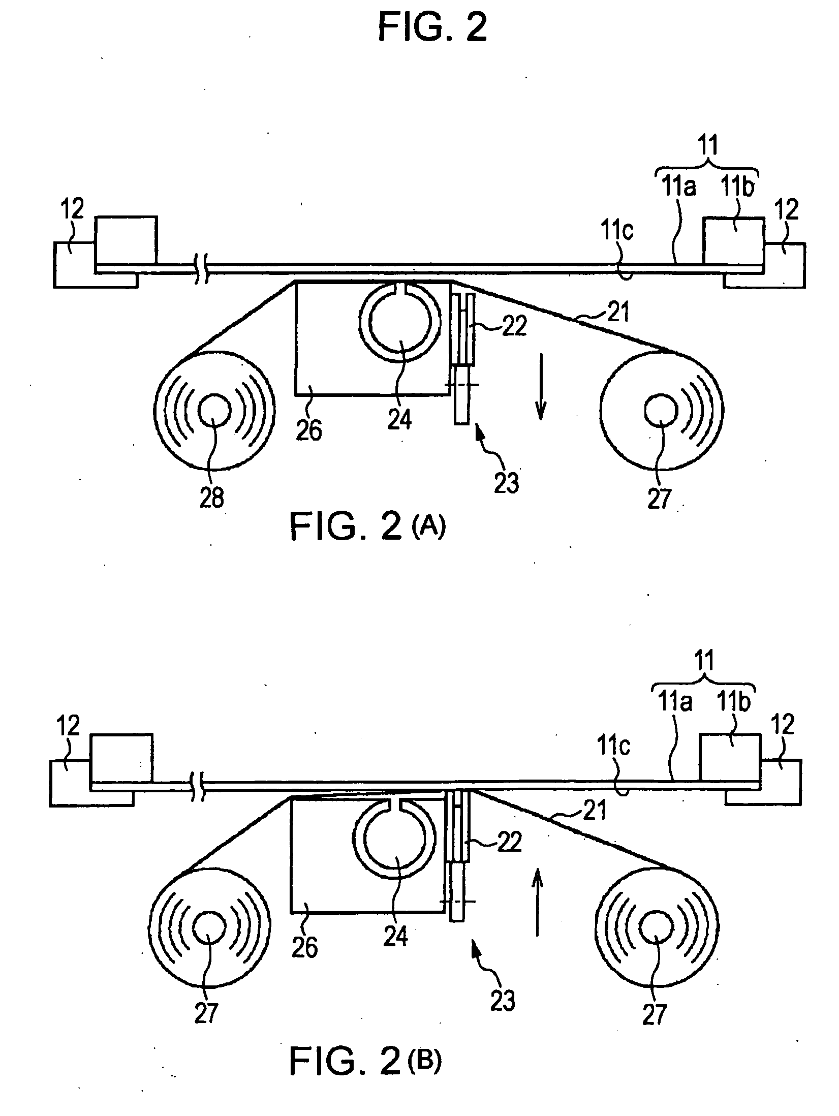
[0012]In the present invention, the cleaning unit includes the scraper that brings the cleaning paper into contact with one surface of the screen mask, that slides on the surface of the screen mask with the cleaning paper being disposed therebetween, and that has the uneven face portion. Hence, cleaning can be performed at a speed higher than in the conventional cleaning method of performing wiping with the cleaning paper. For this reason, it is possible to realize a printing tact in a shorter time than before. Further, cleaning can be performed in every printing step without reducing the printing tact. This allows high-quality printing to be stably performed without lowering the print quality.
[0013]In addition, according to the present invention, since the cleaning paper is slid on the surface of the screen mask with the scraper having the uneven face portion, the amount of paper used in one cleaning step can be reduced.

Problems solved by technology

This leakage occurs particularly when a pasty material having a low viscosity is used, and is a phenomenon in which the residual pasty material drops off from a wall of the aperture because of gravity and flows toward the back surface of the screen mask.
If this adhering residual pasty material is transferred on the printing material, defects in the application position and application shape are caused, and in a circuit board, a quality defect, such as a bridge, is caused.
Further, in printing, if the adhesion between the screen mask and a substrate serving as a printing material is low, the pasty material exudes, and this causes a quality defect. FIG. 11 illustrates a substrate serving as a printing material.
If printing is further performed in a state in which this exudation occurs, defects in application position and application shape and a quality defect, such as a bridge, are caused.
This sacrifices quality.

Method used


Image

  • Cleaning apparatus and screen printing apparatus
  • Cleaning apparatus and screen printing apparatus
  • Cleaning apparatus and screen printing apparatus

Examples


Embodiment Construction

[0025]A specific embodiment of a screen printing apparatus to which the present invention is applied will be described in detail below with reference to the drawings.

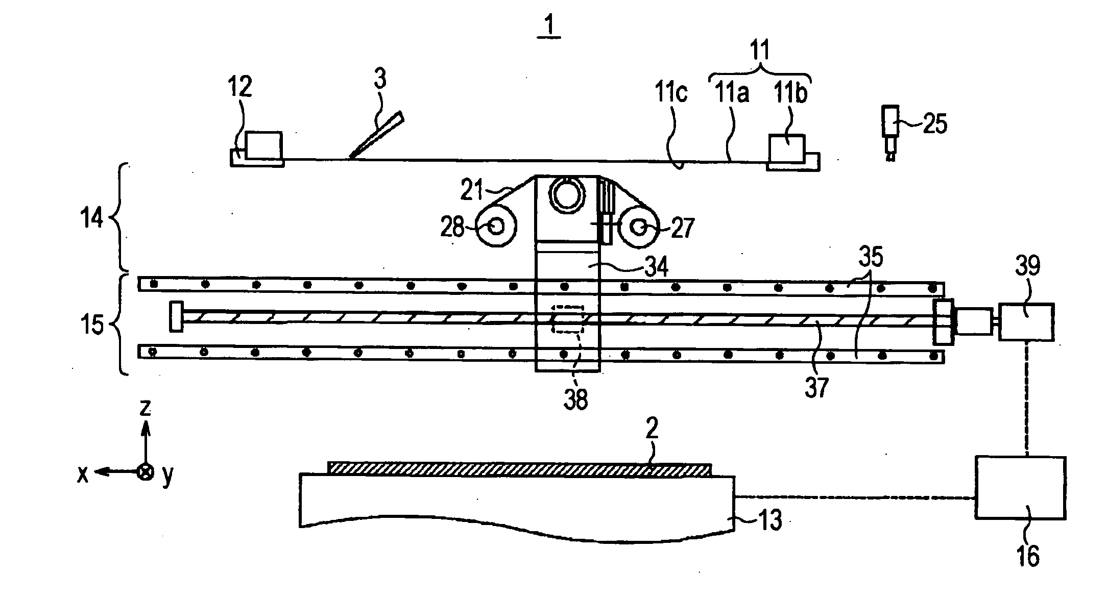
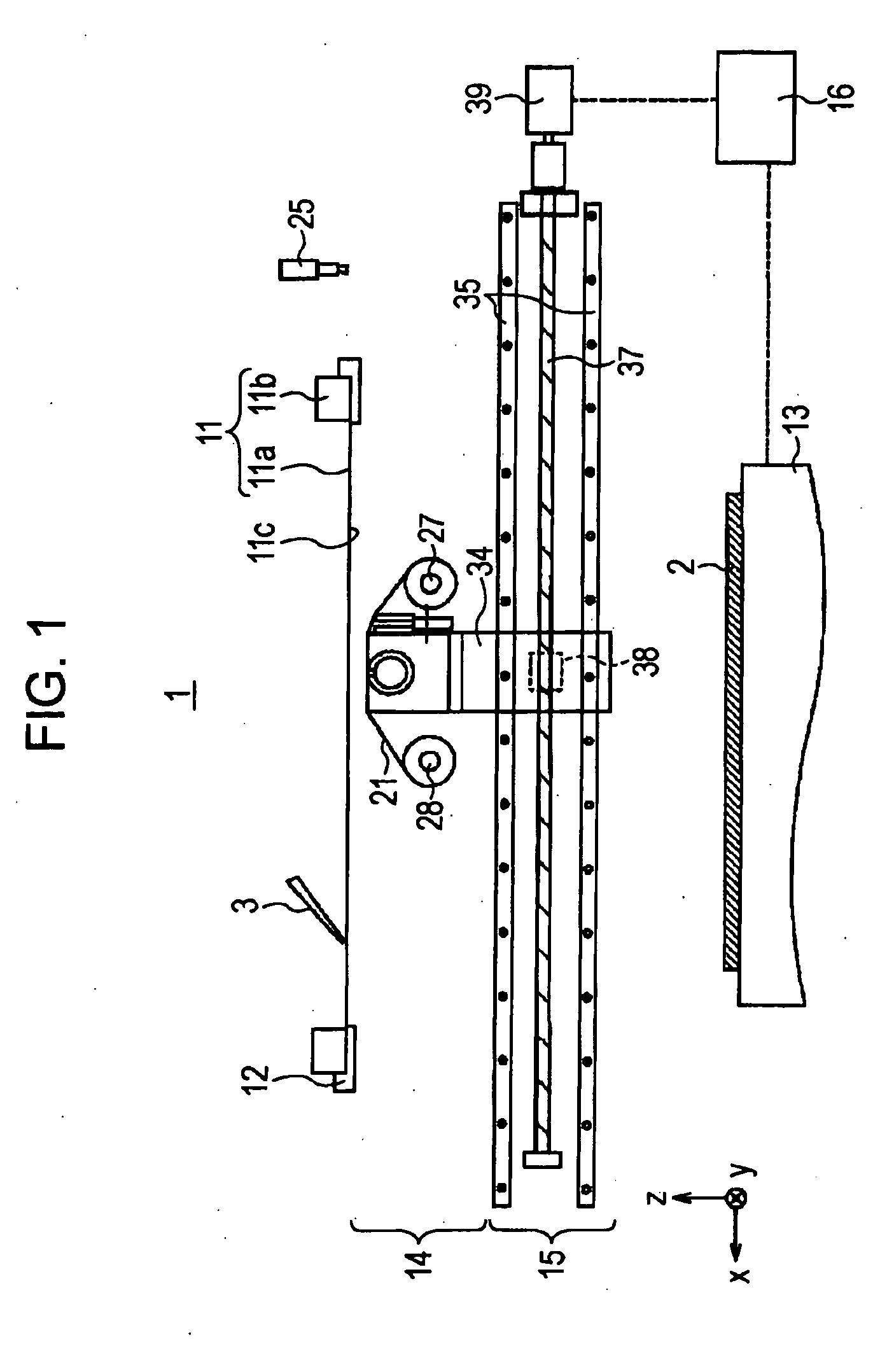
[0026]FIG. 1 is a schematic view of a screen printing apparatus 1 to which the present invention is applied, as viewed from the front side. As illustrated in FIG. 1, the screen printing apparatus 1 includes a screen mask 11 with a print pattern for printing a pattern on a workpiece 2, a screen support portion 12 for supporting the screen mask 11, a stage 13 opposing the screen mask 11 so as to support the workpiece 2, a cleaning unit 14 that is conveyed between the stage 13 and the screen mask 11 so as to clean one surface 11c of the screen mask 11 opposing the workpiece 2, a conveying means 15 for conveying the cleaning unit 14 from one end to the other end of the surface 11c of the screen mask 11, and a control means 16 for controlling operations of the means.

[0027]In the screen printing apparatus 1, the relative posi...


PUM


Abstract

A screen printing apparatus that prevents degradation of a printing tact and print quality is provided. There are included a cleaning unit 14 that cleans one surface 11c of a screen mask 11 opposing a workpiece 2, the screen mask 11 having a print pattern for printing a pattern on the workpiece 2, and a conveying means 15 that conveys the cleaning unit 14 over the surface 11c of the screen mask 11. The cleaning unit 14 includes cleaning paper 21 that contacts the surface 11c of the screen mask 11, a scraper 22 that brings the cleaning paper 21 into contact with the surface 11c of the screen mask 11, that slides on the surface 11c of the screen mask 11 with the cleaning paper 21 being disposed therebetween, and that has an uneven face portion 22b, and a scraper moving means 23 that moves the scraper 22 to the contact position.

Description

TECHNICAL FIELD[0001]The present invention relates to a cleaning device for use in a screen printing apparatus used for a printed wiring board and the like, and to the screen printing apparatus.BACKGROUND ART[0002]Screen printing or the like is used in pattern printing, solder resist printing, numbering printing, and through hole printing in a circuit forming process for a printed wiring board, and solder cream printing and exterior (chassis, name plate, operation panel) printing in a mounting process.[0003]A typical printing machine for performing this screen printing performs printing by applying and transferring a pasty material, such as ink or solder paste, onto a printing surface of a printing material via a screen mask on which a print pattern is drawn. That is, a squeegee is slid on the screen mask, whereby the pasty material is transferred and printed on the printing material. Thus, the pasty material is applied on the printing material through an aperture pattern.[0004]In t...

Claims


Application Information

Patent Timeline
Patent Type & Authority Applications(United States)
IPC IPC(8): B41L13/00B41F35/00
CPCB41F35/005H05K3/26H05K3/1216
Inventor NISHI, EIICHINUMAO, MUNEYOSHI
Owner SONY CORP
Learn More