
Optical fiber current transformer with optical fiber temperature acquisition and temperature compensation

a technology of temperature acquisition and temperature compensation, which is applied in the direction of instruments, heat measurement, measurement devices, etc., can solve the problems of low accuracy of current measurement performed by traditional optical fiber current transformers, and achieve the effect of improving current measurement accuracy

Active Publication Date: 2011-03-10
BEIJING QIRED ELECTRO OPTIC TECH LIMITED
View PDF1 Cites 9 Cited by
  • Summary
  • Abstract
  • Description
  • Claims
  • Application Information

AI Technical Summary

Benefits of technology

[0012]An object of the present invention is to provide an optical fiber current transformer with fiber optical temperature acquisition and temperature compensation, which can improve the current measurement accuracy to be as high as 0.1%.
[0014]The optical fiber current transformer with fiber optic temperature acquisition and temperature compensation of the present invention has the following advantages.
[0015](1) The present invention adopts the dual mode, with calculating compensation unit and data processing unit. The data processing for temperature and the current are carried out in different processors, and synchronized in the calculating compensation unit, thereby improving the accuracy of real-time current measurement of the optical fiber current transformer. The accuracy of the current measurement can be as high as 0.1%.
[0017](3) Modularization of the sensor system clearly distinguishes the function of each module. Accordingly, the faulting module can be easily detected while a fault occurs, thereby facilitating maintenance.
[0018](4) The optical fiber current transformer of the present invention adopts two processors and hardware / software modularization, thereby facilitating the forming of single-phase optical fiber current transformers and tri-phase optical fiber current transformers.
[0019](5) In a tri-phase optical fiber current transformer, the calculating compensation unit deals with the input data of three-phase temperature and three-phase current by a simple first-in-first-out mode, thereby improving the system response time to the output current.

Problems solved by technology

Therefore, the measurement of current performed by traditional optical fiber current transformers is low-accuracy due to the temperature effects of the sensor systems.

Method used


Image

  • Optical fiber current transformer with optical fiber temperature acquisition and temperature compensation
  • Optical fiber current transformer with optical fiber temperature acquisition and temperature compensation
  • Optical fiber current transformer with optical fiber temperature acquisition and temperature compensation

Examples


Embodiment Construction

[0025]The present invention is further explained with the accompanying drawings.

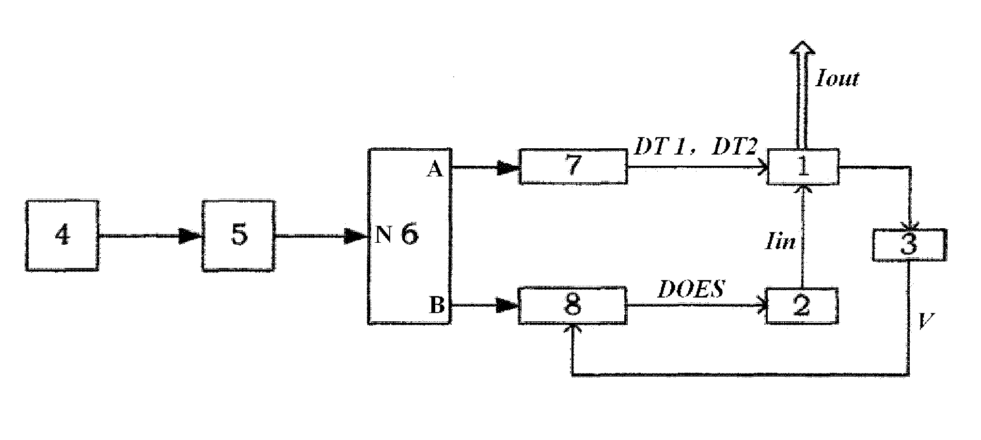
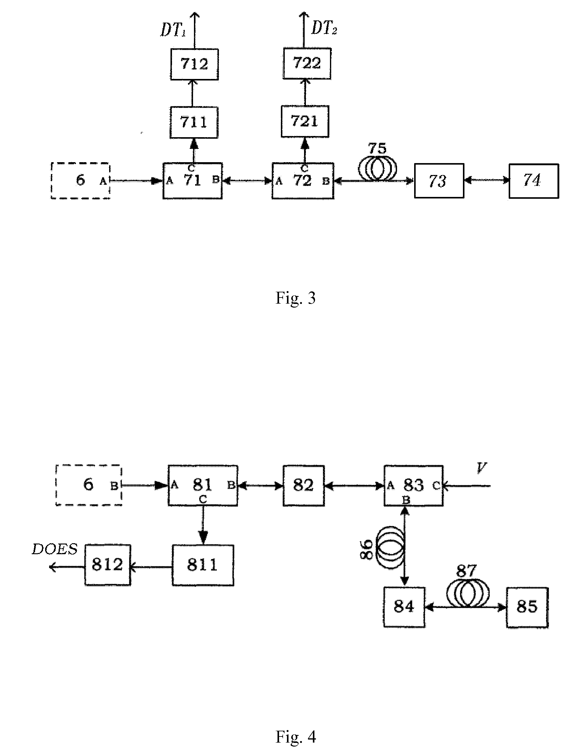
[0026]Referring to FIG. 1, an optical fiber current transformer with optical fiber temperature acquisition and temperature compensation according to a preferred embodiment of the present invention is illustrated, wherein the optical fiber current transformer comprises a broadband light source 4, a depolarizer 5, a beam splitter 6, a temperature acquisition unit 7, a current acquisition unit 8, a modulation waveform generating unit 3, a data processing unit 2 and a calculating compensation unit 1. The calculating compensation unit 1 consists of an IC hardware and a two-temperature source compensation software module compiled in the IC hardware. The IC hardware can be a DSP processor chip, a single chip microcomputer or a microprocessor. The data processing unit can be an FPGA processor.

[0027]The broadband light source 4 is connected with the input port N of the beam splitter 6 through the depolarizer 5.

[0...


PUM


Abstract

An optical fiber current transformer includes a broadband light source, a depolarizer, a beam splitter, a temperature acquisition unit, a current acquisition unit, a modulation waveform generating unit, a data processing unit and a calculating compensation unit. The broadband light source is connected with the beam splitter by the depolarizer. A first output of the beam splitter is connected with the calculating compensation unit by the temperature acquisition unit. A second output of the beam splitter is connected with the data processing unit by the current acquisition unit. The data processing unit is connected with the calculating compensation unit. The calculating compensation unit is connected with the current acquisition unit by the modulation waveform generating unit. The optical fiber current transformer uses the temperature-current compensation curve in the calculating compensation unit to synchronously process the temperature and current, thereby improving the accuracy of real-time current measurement.

Description

BACKGROUND OF THE PRESENT INVENTION[0001]1. Field of Invention[0002]The present invention relates to an optical fiber current transformer, and more particularly to an optical fiber current transformer with two-temperature source compensation mode.[0003]2. Description of Related Arts[0004]The optical fiber current transformer is based on the Ampere's law and Faraday magneto-optical effect. It can indirectly measure the current value by measuring the phase difference, induced by the current magnetic field, between two orthogonally polarized light beams transmitting in the sensing fiber.[0005]For optical fiber current transformers applied in the electrical power network, the environment temperature effects on the measured current value may include[0006]1. The variation of magneto-optical coefficient with the change of temperature;[0007]2. The retardation of fiber optic wave plate changes with the change of temperature;[0008]3. The internal strain in the sensing fiber may vary with the ...

Claims


Application Information

Patent Timeline
Patent Type & Authority Applications(United States)
IPC IPC(8): G06F19/00
CPCG01K11/00G01R19/32G01R15/247
Inventor WU, SHUDONGWANG, WENBO
Owner BEIJING QIRED ELECTRO OPTIC TECH LIMITED
Learn More