
Delamination resistant packaged die having support and shaped die having protruding lip on support

Active Publication Date: 2011-03-10
TEXAS INSTR INC
View PDF5 Cites 9 Cited by
  • Summary
  • Abstract
  • Description
  • Claims
  • Application Information

AI Technical Summary

Benefits of technology

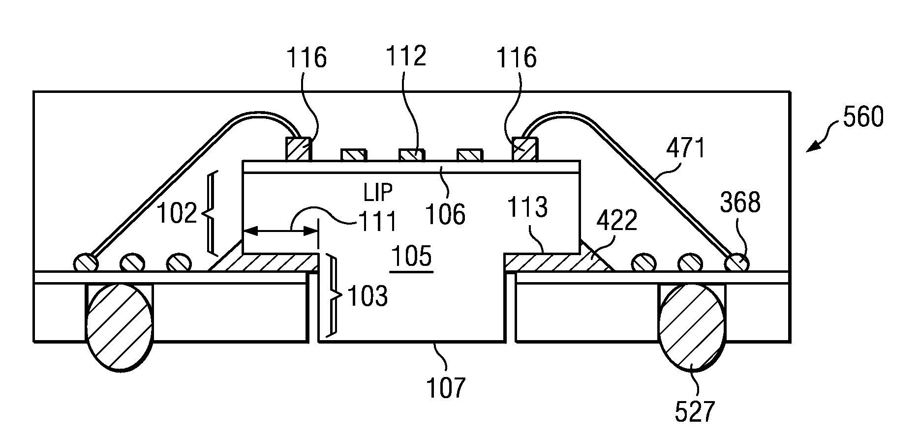
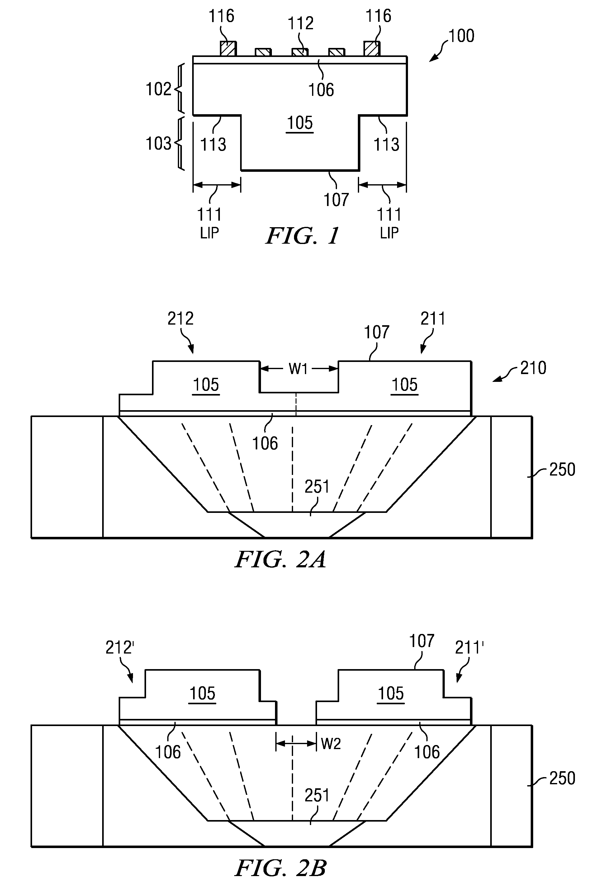
[0009]Since only a small radially outward portion of the area of the thickness shaped IC die is in contact with the die support structure, that being the protruding lip of the thickness shaped IC die, disclosed embodiments reduce differential CTE induced delamination of the IC die from the die support structure. Disclosed embodiments also overcome problems associated with conventional exposed silicon packages include bleeding of the die attach adhesive (e.g., epoxy) onto the top active circuitry comprising surface of the IC die which can result in bonding and reliability problems, as well as die tilt which reduces mold flush and die cracking.
[0010]Moreover, the mold lock provided by disclosed embodiments solve the reliability (e.g., delamination) problem that plagues all exposed silicon packages associated with ambient moisture penetration through the package to reach the thickness shaped IC die. Reducing or eliminating ambient moisture penetration through the package to reach the thickness shaped IC die reduces reliability problems including delamination associated with moisture penetration.

Problems solved by technology

Delamination of a packaged IC die from its mounting surface, which is commonly triggered by die attach stress, is a known problem.
However, such arrangements generally have poor thermal performance due to the high thermal resistance of the epoxy-mold compound of the package that is between the IC and a heat sink (e.g. the ambient) in such arrangements.
Exposed silicon packages have several known problems.
Problems for conventional exposed silicon packages include bleeding of the die attach adhesive (e.g., epoxy) onto the top surface of the IC die which can result in bonding and reliability problems, as well as die tilt.
Die tilt can cause leakage of molding resin commonly referred to in the art as “mold flush”, as well as die cracking.
In addition, both conventional exposed silicon packages and the alternate arrangement described above do not provide a mold lock to the IC substrate (e.g., silicon), so that ambient moisture can enter the packaged IC and reach the IC die, and as a result can cause reliability problems including delamination.
Disclosed embodiments also overcome problems associated with conventional exposed silicon packages include bleeding of the die attach adhesive (e.g., epoxy) onto the top active circuitry comprising surface of the IC die which can result in bonding and reliability problems, as well as die tilt which reduces mold flush and die cracking.
Reducing or eliminating ambient moisture penetration through the package to reach the thickness shaped IC die reduces reliability problems including delamination associated with moisture penetration.
This embodiment also overcome problems associated with conventional exposed silicon packages include bleeding of the die attach adhesive (e.g., epoxy) onto the top active circuitry comprising surface of the IC die which can result in bonding and reliability problems, as well as die tilt which reduces mold flush and die cracking.
This embodiment also overcomes problems associated with conventional exposed silicon packages include bleeding of the die attach adhesive (e.g., epoxy) onto the top active circuitry comprising surface of the IC die which can result in bonding and reliability problems, as well as die tilt.

Method used


Image

  • Delamination resistant packaged die having support and shaped die having protruding lip on support
  • Delamination resistant packaged die having support and shaped die having protruding lip on support
  • Delamination resistant packaged die having support and shaped die having protruding lip on support

Examples


Embodiment Construction

[0019]Disclosed embodiments are described with reference to the attached figures, wherein like reference numerals are used throughout the figures to designate similar or equivalent elements. The figures are not drawn to scale and they are provided merely to illustrate the disclosed embodiments. Several disclosed aspects are described below with reference to example applications for illustration. It should be understood that numerous specific details, relationships, and methods are set forth to provide a full understanding of the disclosed embodiments. One having ordinary skill in the relevant art, however, will readily recognize that embodiments of the invention can be practiced without one or more of the specific details or with other methods. In other instances, well-known structures or operations are not shown in detail to avoid obscuring the disclosure. The disclosed embodiments are not limited by the illustrated ordering of acts or events, as some acts may occur in different or...


PUM

PropertyMeasurementUnit
Fractionaaaaaaaaaa
Thicknessaaaaaaaaaa
Electrical conductoraaaaaaaaaa

Abstract

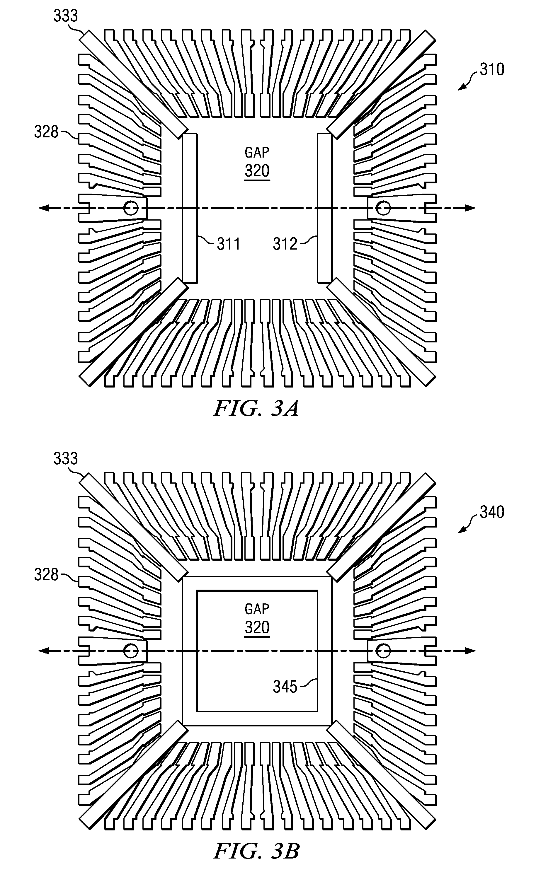
A packaged electronic device includes a thickness shaped IC die including a top portion, top surface, active circuitry, bottom portion and bottom surface. A cross sectional area of the bottom surface is ≧5% less than a cross sectional area of the top surface to provide a protruding lip having a bottom lip surface. A package substrate includes a top substrate surface including substrate bonding sites, a bottom substrate surface, and a die support structure on the top substrate surface having a gap region. The bottom lip surface of the IC die is secured to the die support structure and the bottom surface of the IC die extends below the die support structure into the gap region. Coupling connectors couple the bonding features on the IC die to the substrate bonding sites.

Description

FIELD[0001]Disclosed embodiments relate to assembly and packaging of electronic devices including integrated circuit (IC) die, and more particularly, to delamination resistant packaged electronic devices including exposed IC substrate (e.g., silicon) embodiments.BACKGROUND[0002]Delamination of a packaged IC die from its mounting surface, which is commonly triggered by die attach stress, is a known problem. One type of die attach stress (generally referred to as “differential coefficients of thermal expansion (CTE) stress”) is induced by heating (or cooling) a packaged IC die that arises from forces produced by the large differential CTE between the IC die and the die mounting surface (e.g., a die attach pad) that is often present, such as when the IC die comprises silicon and the die pad comprises copper.[0003]A window pad type of lead frame is a type of lead frame that is used for construction of electronic packages. This type of lead frame is characterized by an opening (or “windo...

Claims


Application Information

Patent Timeline
IPC IPC(8): H01L23/495H01L21/78H01L23/00H05K3/20
CPCH01L23/13H01L23/3107H01L23/3128H01L23/49503H01L23/49513H01L23/49816H01L24/05H01L24/29H01L24/32H01L24/48H01L24/83H01L29/0657H01L2224/2919H01L2224/32014H01L2224/32245H01L2224/48091H01L2224/48227H01L2224/48247H01L2224/48475H01L2224/73265H01L2224/83192H01L2224/83194H01L2224/8385H01L2224/85051H01L2224/92247H01L2924/01005H01L2924/01029H01L2924/01047H01L2924/01082H01L2924/07802H01L2924/10158H01L2924/10253H01L2924/14H01L2924/15311H01L2924/18165H01L2924/19041H01L2224/32225H01L2224/4848H01L2924/01006H01L2924/01033H01L2924/014H01L2924/0665H01L2224/29101H01L2924/1461Y10T29/49128H01L2924/00014H01L2924/00012H01L2924/00H01L2924/3512H01L24/73H01L2224/29035H01L2224/32105H01L2924/10156H01L2924/15151H01L2924/15153H01L2924/181H01L2924/35121H01L2224/45099H01L2224/85399H01L2224/05599
Inventor FENG, CHIEN-TEANO, KAZUAKIYU, FRANKLIU, TREVOR
Owner TEXAS INSTR INC
Learn More