Microembolic signals detection during cordiopulmonary bypass

Inactive Publication Date: 2011-03-03
ZANATTA PAOLO
View PDF2 Cites 22 Cited by
  • Summary
  • Abstract
  • Description
  • Claims
  • Application Information

AI Technical Summary

Problems solved by technology

Unfortunately, TCD usually requires a dedicated person specifically trained in its use to be in attendance during its use.
Often, cardiac surgery is performed on short notice and people trained in TCD may not be available.
Therefore, either a short-notice surgery will have to be delayed, or the surgery will have to proceed without microemboli detection.

Method used


Image

  • Microembolic signals detection during cordiopulmonary bypass
  • Microembolic signals detection during cordiopulmonary bypass
  • Microembolic signals detection during cordiopulmonary bypass

Examples


Embodiment Construction

[0016]A preferred embodiment of the invention is now described in detail. Referring to the drawings, like numbers indicate like parts throughout the views. Unless otherwise specifically indicated in the disclosure that follows, the drawings are not necessarily drawn to scale. As used in the description herein and throughout the claims, the following terms take the meanings explicitly associated herein, unless the context clearly dictates otherwise: the meaning of “a,”“an,” and “the” includes plural reference, the meaning of “in” includes “in” and “on.”

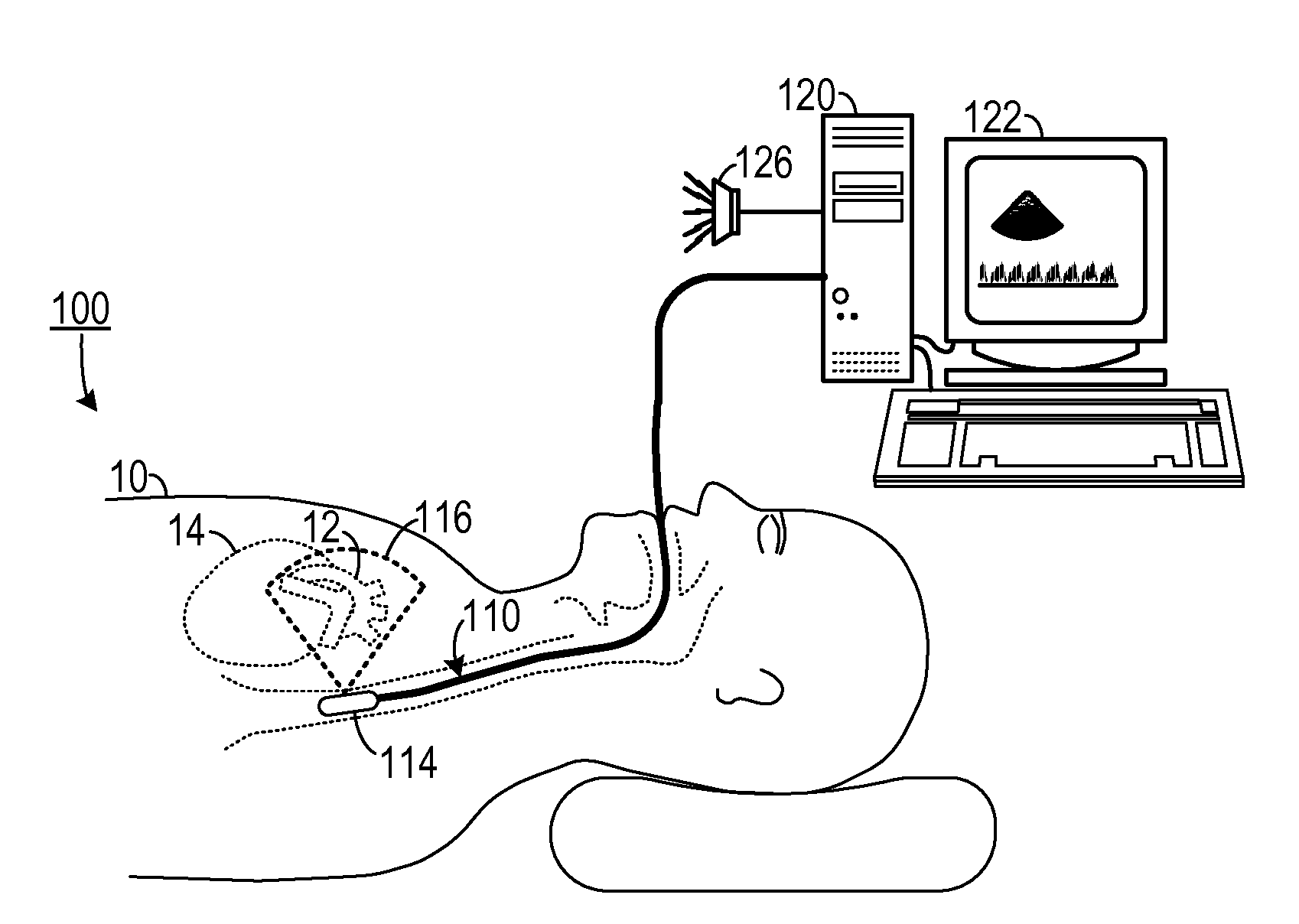
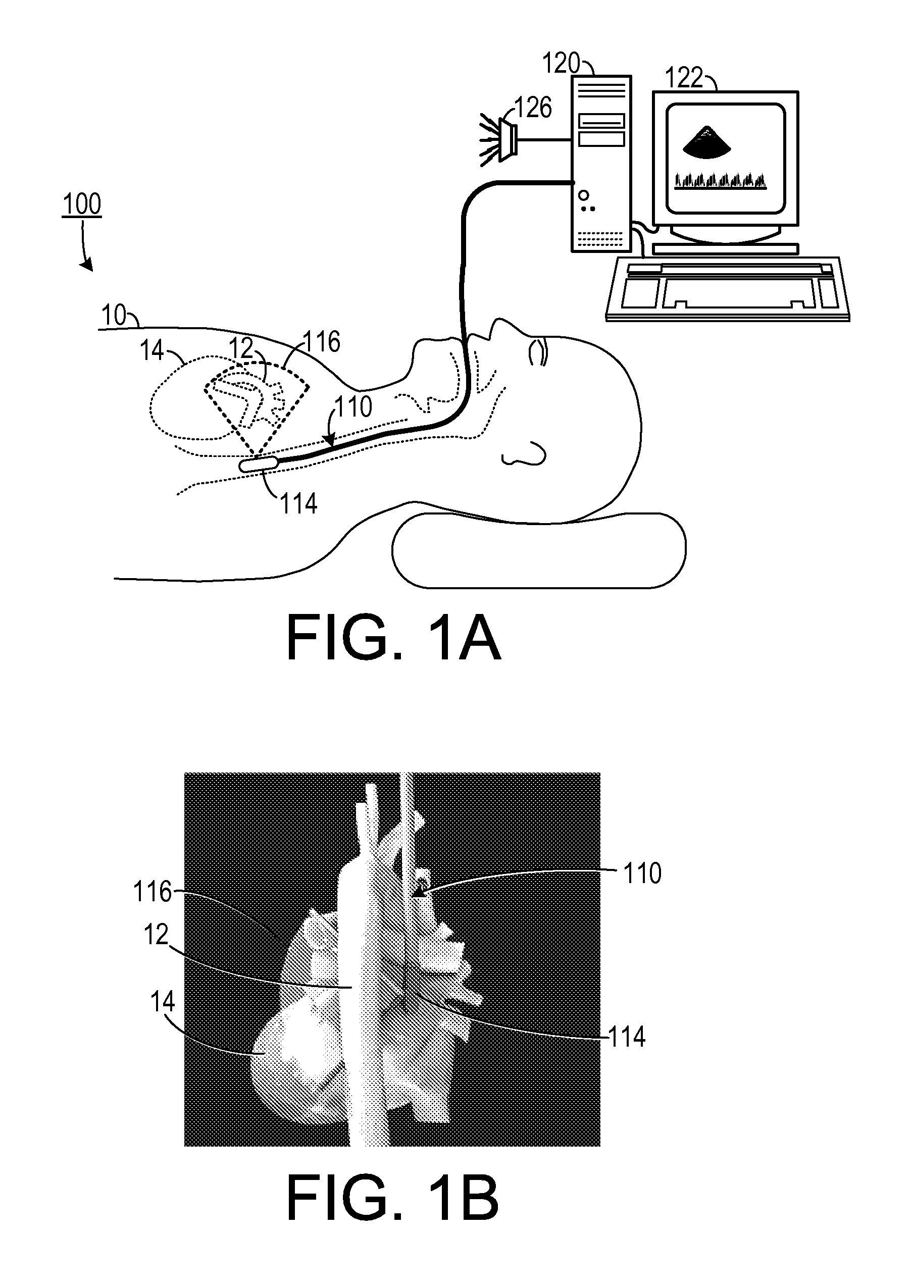
[0017]As shown in FIGS. 1A-1B, in one embodiment, one method of detecting microembolic signals in the aorta 12 of a patient 10 during heart surgery includes inserting, through the mouth of the patient 10, a transoesophageal echo device (TEE) 110 having in the distal portion an ultrasound transducer 114. The TEE device 110 is configured to perform a bidimensional or tridimensional evaluation and echocolor Doppler of the heart and the ao...


PUM


Abstract

In a method of detecting microemboli in a patient, an echography probe is applied to a selected location of the patient. An ultrasonic signal is sensed with the echocardiography probe. The ultrasonic signal is processed with a processor to determine a systemic embolic load in the selected location. A representation of a systemic embolic load indicated by the ultrasonic signal is presented to a user.

Description

CROSS-REFERENCE TO RELATED APPLICATION(S)[0001]This application claims the benefit of U.S. Provisional Patent Application Ser. No. 61 / 238,923, filed Sep. 1, 2009, the entirety of which is hereby incorporated herein by reference.BACKGROUND OF THE INVENTION[0002]1. Field of the Invention[0003]The present invention relates to cardiac surgical systems and, more specifically, to a system for detecting microembolic signals during cardiopulmonary bypass and other surgical procedures.[0004]2. Description of the Related Art[0005]Microembolic injuries are one of the determining factors to cognitive dysfunction after cardiac surgery as hypoperfusion, iper-rewarming and inflammation due to cardiopulmonary bypass. Transcranial Doppler (TCD) is one method used to determine the occurrence and the frequency of cerebral microembolic signals during different kinds of cardiac surgery. Thus, TCD may alert the surgical team when microemboli enter into the cerebral circulation during surgery, thus allowi...

Claims


Application Information

Patent Timeline
IPC IPC(8): A61B8/14
CPCA61B8/12A61B5/02007
Inventor ZANATTA, PAOLO
Owner ZANATTA PAOLO
Why Eureka
Try Eureka