Outer mirror with turn lamp

Active Publication Date: 2011-03-03
MURAKAMI CORP
View PDF11 Cites 4 Cited by
  • Summary
  • Abstract
  • Description
  • Claims
  • Application Information

AI Technical Summary

Benefits of technology

[0008]The present invention provides an outer mirror with turn lamp having a structure in which with a turn lamp assembly being mounted to a mirror housing, a housing cover is placed over and mounted to a partial area of the mirror housing, and a lens of the turn lamp assembly is exposed through an opening with a closed entire circumference formed in an outer position of the housing cover, wherein the mirror housing and the housing cover are connected to each other with end surfaces being abutted against each other, a groove is formed in an abutting end surface of the housing cover, a ridge that fits into the groove is formed in an abutting end surface of the mirror housing, and on a wall on an inner side of the mirror among inner and outer walls that constitute the groove in the housing cover, at an assembling start position in an outer position outside the opening, an assembling leading rib is formed that protrudes in a direction abutting against the abutting end surface of the mirror housing and first leads the ridge in the abutting end surface of the mirror housing into the groove at the assembling start position. According to this, the ridge in the abutting end surface of the mirror housing can be slid on a surface of the assembling leading rib and led into the groove at the assembling start position, thereby allowing the groove and the ridge to be easily fitted to each other at the assembling start position. Also, the assembling leading rib is formed in the outer position outside the opening in the housing cover, thereby increasing strength of the outer position outside the opening in the housing cover and preventing fitting between the groove and the ridge from being released when an impact is applied to the housing cover.
[0009]The assembling leading rib may have a length longer than a width of the opening, and be formed to extend to both sides of an area of the opening. This can further increase strength of the outer position outside the opening in the housing cover, and more reliably prevent fitting between the groove and the ridge from being released when an impact is applied to the housing cover.
[0011]The plurality of protrusions may be placed such that the interval increases along with the distance from the assembling leading rib. Specifically, as fitting between the groove and the ridge proceeds, misalignment between the groove and the ridge is less likely to occur in positions ahead of the fitted position, and thereby the groove and the ridge easily fit each other even if the intervals between the protrusions gradually become larger. This can eliminate the need for providing unnecessary protrusions, reduce the number of recesses for forming the protrusions, which are formed in a die for forming the housing cover, and reduce the number of steps for machining the die.

Problems solved by technology

In the outer mirror with turn lamp described in Japanese Patent Laid-Open No. 2006-290184, the groove and the ridge are uniformly formed along abutting end surfaces of the mirror housing and the housing cover, and fitting between the groove and the ridge at an assembling start position is difficult in assembling the housing cover to the mirror housing.
Even after the fitting between the groove and the ridge at the assembling start position, fitting between the groove and the ridge across the entire area is difficult, and the mirror housing and the housing cover are often connected to each other with the groove and the ridge partially not fitting each other.

Method used


Image

  • Outer mirror with turn lamp
  • Outer mirror with turn lamp
  • Outer mirror with turn lamp

Examples


Embodiment Construction

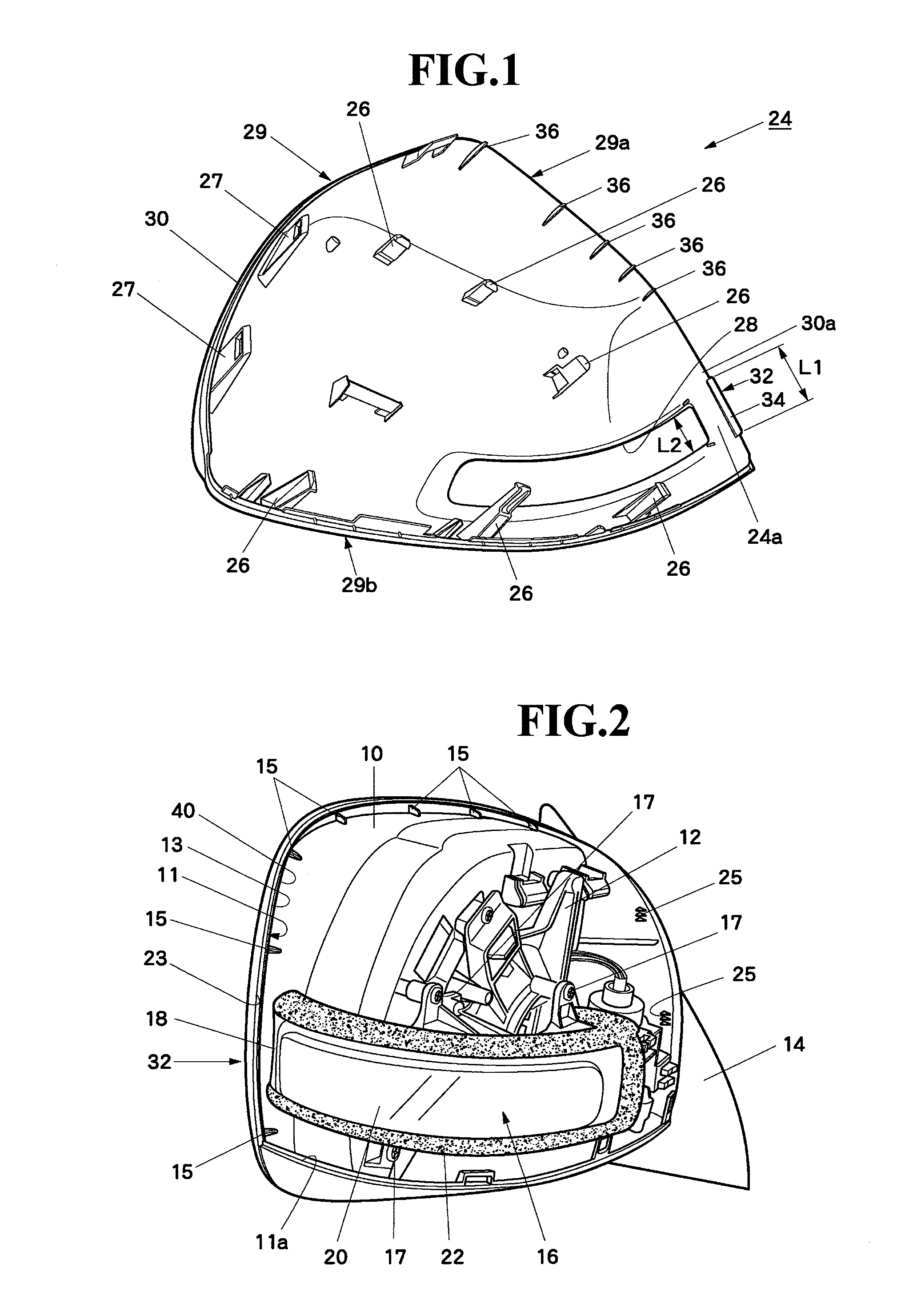
[0020]An embodiment of the present invention will be described. FIG. 2 shows a vehicle right side door mirror of the present invention viewed from an obliquely back side with a housing cover being removed. A frame 12 made of metal or glass fiber reinforced rigid plastic is removably mounted to a back surface of a plastic mirror housing 10 by threading screws from a front side of the mirror housing 10. The mirror housing 10 is supported by a mirror base 14 pivotably in retracting and returning directions. The mirror base 14 is mounted to a vehicle body (right door).

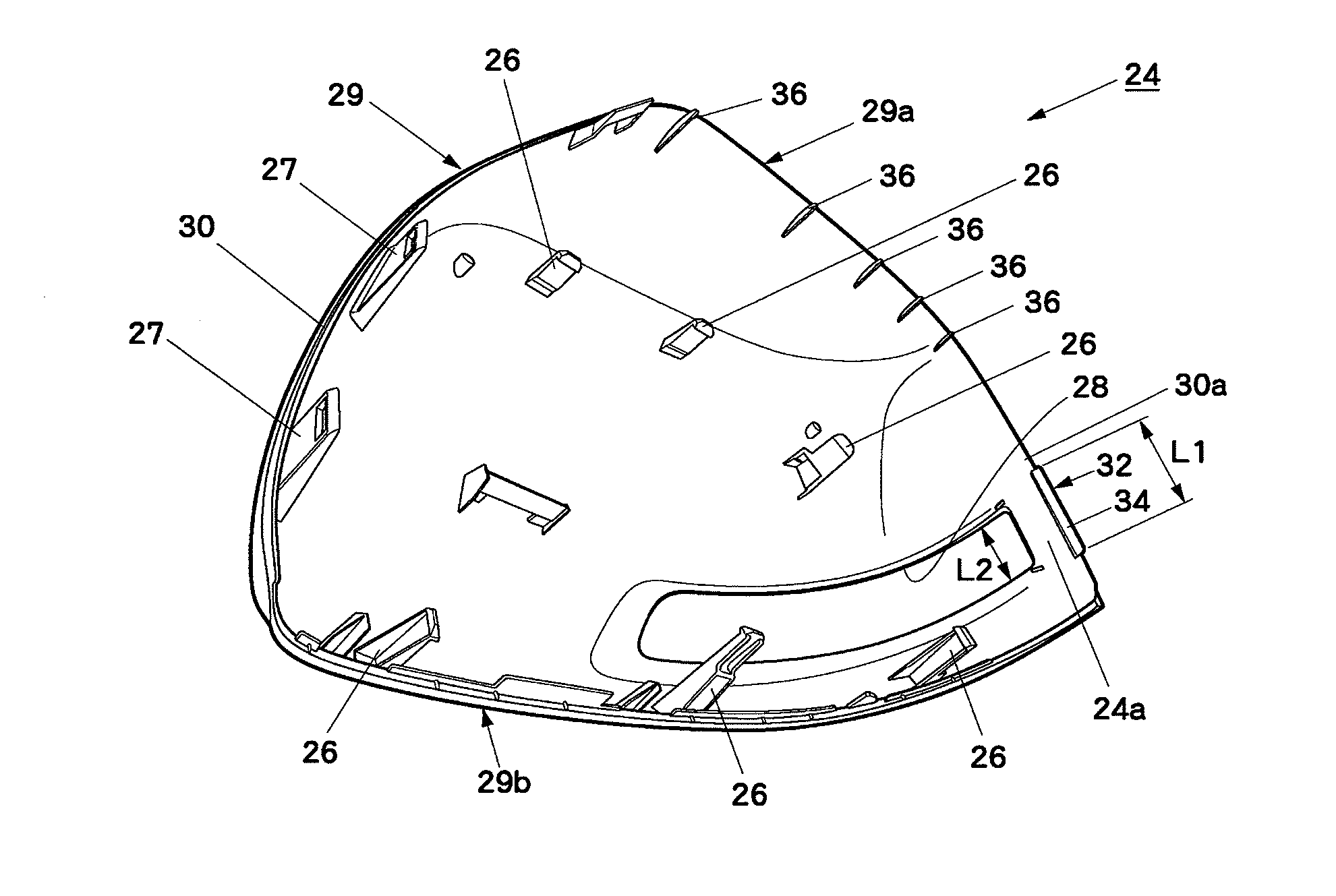
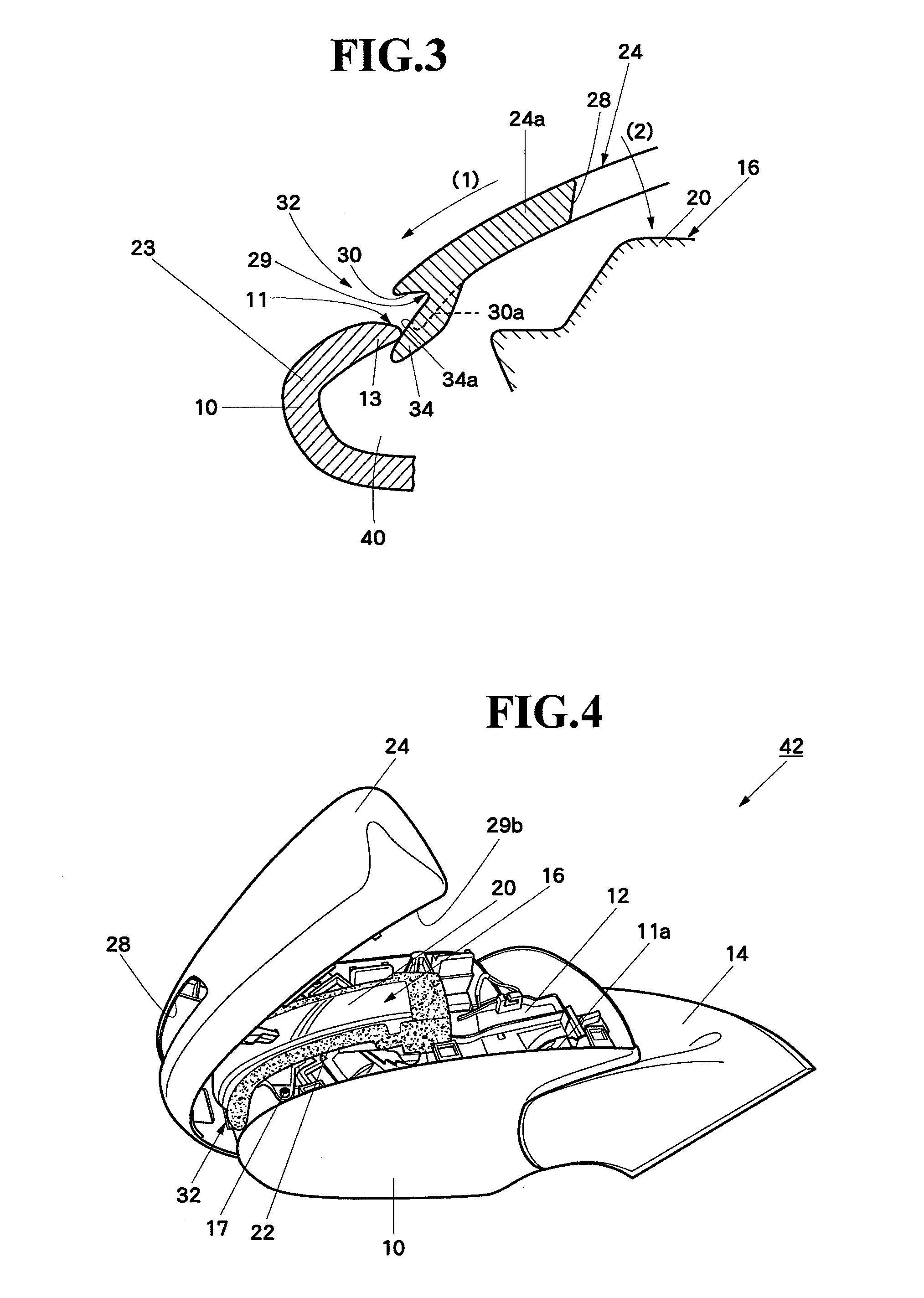
[0021]An end surface 11 (surface abutting against an end surface 29 of the housing cover 24) of a peripheral edge of an area over which the housing cover 24 (FIG. 1) is placed of the mirror housing 10 is folded back outward except in a lower side 11a to constitute a folded portion 23. As shown in FIG. 7, the end surface 11 of the folded portion 23 constitutes a ridge 13. In a recess 40 formed on a back side of the folded p...


PUM


Abstract

There is provided an outer mirror with turn lamp that facilitates assembling of a housing cover to a mirror housing and increases strength of the housing cover. A turn lamp assembly is mounted to a mirror housing. A housing cover is placed over and mounted to a partial area of the mirror housing. Thus, a lens of the turn lamp assembly is exposed through an opening formed in an outer position of the housing cover. The mirror housing and the housing cover are connected to each other with a ridge and a groove in end surfaces and abutting against and fitting each other. On a wall on an inner side of the mirror that constitutes a part of the component of the groove in the housing cover, at an assembling start position in an outer position outside the opening, an assembling leading rib is formed that protrudes in a direction abutting against the end surface of the mirror housing.

Description

[0001]The disclosure of Japanese Patent Application No. JP2009-200842 filed on Aug. 31, 2009 including the specification, drawings, claims and abstract is incorporated herein by reference in its entirety.BACKGROUND OF THE INVENTION[0002]1. Field of the Invention[0003]The present invention relates to an outer mirror with turn lamp that has a structure in which with a turn lamp assembly being mounted to a mirror housing, a housing cover is placed over and mounted to a partial area of the mirror housing, and a lens of the turn lamp assembly is exposed through an opening with a closed entire circumference formed in an outer position of the housing cover, and facilitates assembling of the housing cover to the mirror housing and increases strength of the housing cover.[0004]2. Description of the Related Art[0005]An outer mirror with turn lamp having the above-described structure is described in Japanese Patent Laid-Open No. 2006-290184. This outer mirror with turn lamp has a structure in ...

Claims


Application Information

Patent Timeline
IPC IPC(8): B60R1/12
CPCB60R1/1207B60Q1/2665
Inventor MURATA, YOSHIHIRO
Owner MURAKAMI CORP
Why Eureka
Try Eureka