Pin impactor

Active Publication Date: 2016-07-26
DEPUY (IRELAND) LTD
View PDF28 Cites 0 Cited by
  • Summary
  • Abstract
  • Description
  • Claims
  • Application Information

AI Technical Summary

Benefits of technology

The present invention is a multi-pin pin impactor that can be used to apply a driving force to a pin by releasably retaining the pin in a re-positionable manner. The pin impactor has a body holdable by a user and manipulable to re-position the pin during use. It includes a first pin holder with a first pin release mechanism and a second pin holder with a second pin release mechanism. The pin impactor can hold multiple pins in a releasable fashion, reducing the need for re-loading during use and making surgery quicker and safer. It can be designed to prevent fouling and can have a geometry that reduces the chance of injury or damage to gloves or instrumentation. The pin impactor can have a composite construction with a core of a first material and a coating of a second material. The invention also provides a kit of parts and an assembly for use in surgical procedures.

Problems solved by technology

However, having to re-load the pin impactor introduces delays and difficulties into surgery.
If the pin impactor is reloaded by another person, then the surgeon can pass the pin impactor to them for reloading and then wait for it to be reloaded and passed back, again adding delays and more handling of sharps, as the pin tip is sharp.
Alternatively, the surgeon can hold the empty pin impactor, while another person places a second pin in the impactor, but that can be a very fiddly manual activity as the pins can have small diameters and again requires the handling of sharps and so is potentially dangerous.
An alternative is simply to have multiple pin impactors each pre-loaded with a single pin, but that again introduces delays as each pin impactor is passed to and from the surgeon and also introduces more sharps and more sharps handling and also adds more instrumentation to an area already full of instruments.

Method used


Image

  • Pin impactor
  • Pin impactor
  • Pin impactor

Examples


Embodiment Construction

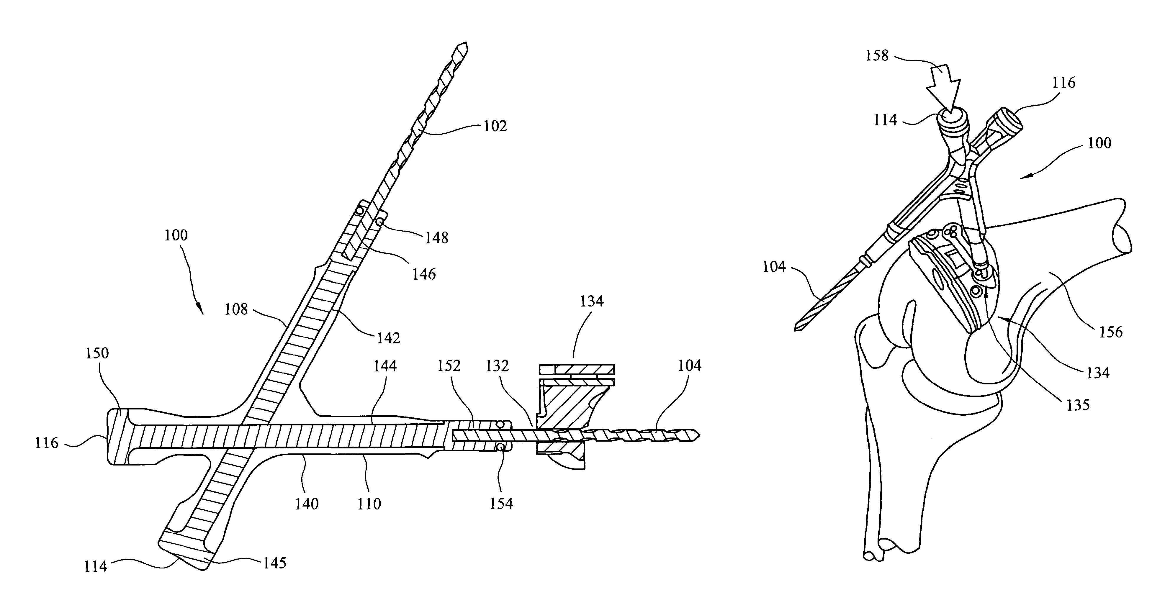
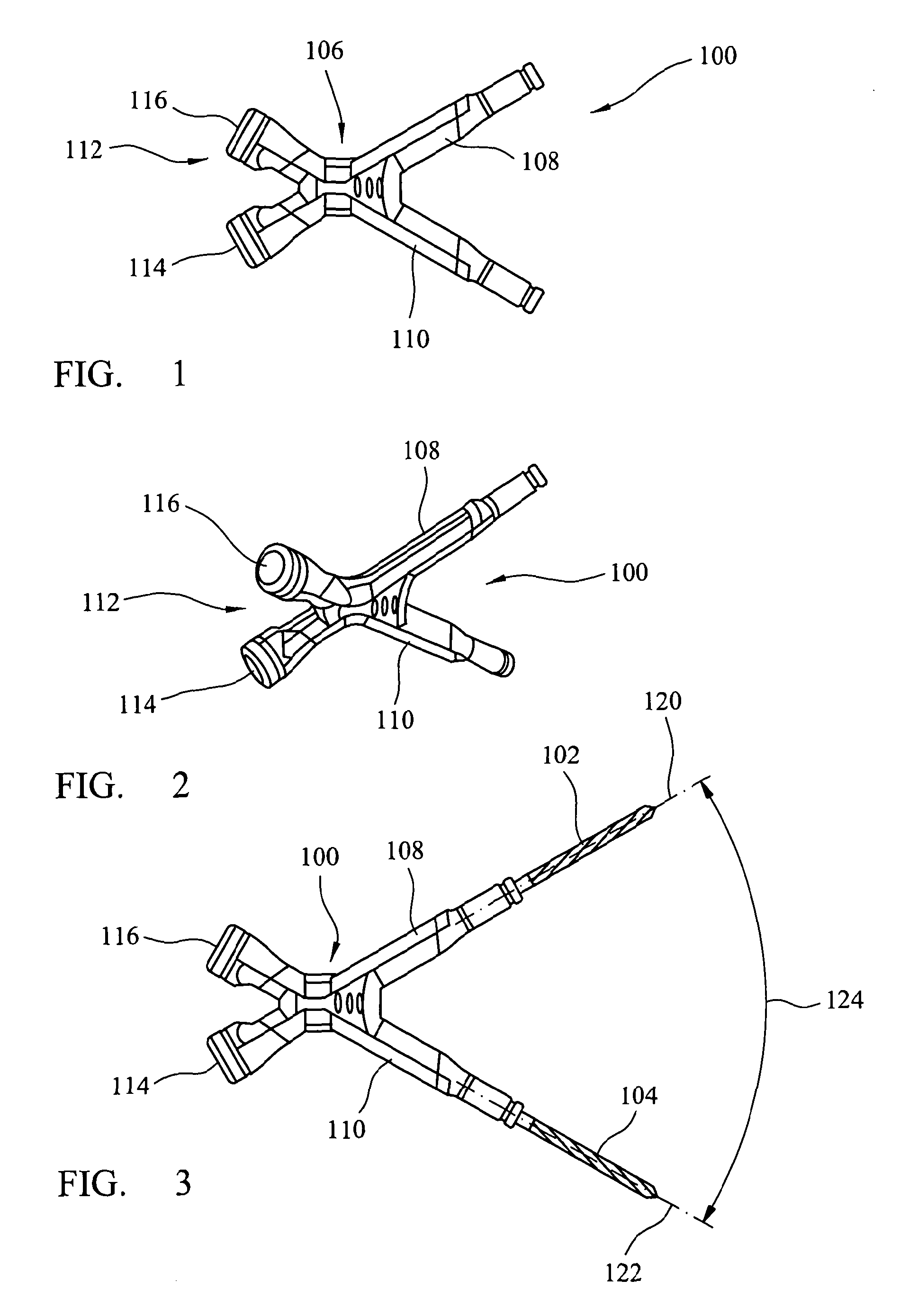
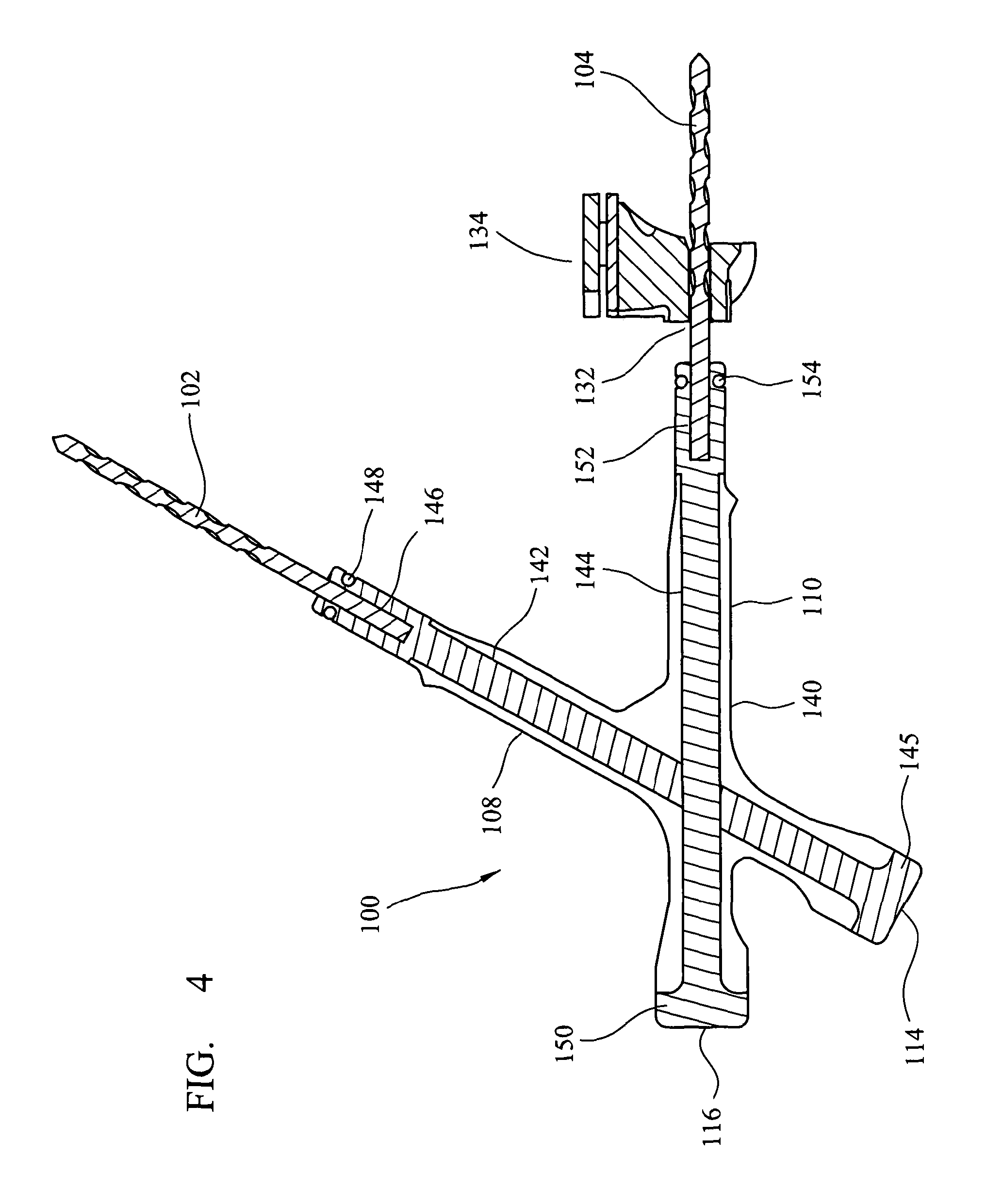
[0038]With reference to FIG. 1, there is shown a side view, a multi-pin pin impactor 100 according to the present invention. FIG. 2 shows a perspective view of the pin impactor 100 from the rear. FIG. 3 shows a side view of an assembly comprising the pin impactor 100 loaded with a first pin 102 and a second pin 104 as will be described in greater detail below.

[0039]As illustrated in FIG. 1, the pin impactor 100 includes a body portion 106 from which a first pin holder 108 and a second pin holder 110 extend. The pin impactor 100 also includes an impacted portion 112 disposed on a generally opposite side of the pin impactor to the pin holders. The impaction portion includes a first impaction surface 114 associated with the first pin holder 108, and a second impaction surface 116 associated with the second pin holder 110.

[0040]As illustrated in FIGS. 1 to 3, the pin impactor has a generally ‘X’ shape and the pin holders lie in a common plane. As illustrated in FIG. 3, the first pin hol...


PUM


Abstract

A multi-pin pin impactor and method of use are described. The pin impactor includes a body which can be held by a user and manipulated to re-position the pin impactor during use. First and second pin holders are attached to the body and each include a pin release mechanism effective to releasably retain a pin within the pin holder. An impaction can have a force applied to apply a driving force to a one of the pins. In use, a first pin held by the pin impactor is introduced into an aperture in a surgical instrument mounted on a bone. A force is applied to the pin impactor to drive the first pin into the bone. The orientation or position of the pin impactor is changed to introduce a second pin held by the pin impactor into a second aperture in the surgical instrument without re-loading the pin impactor and a force is applied to the pin impactor to drive the second pin into the bone.

Description

CROSS REFERENCE TO RELATED APPLICATION[0001]This application is a National Stage 35 U.S.C. 371 of International Patent Application PCT / GB2011 / 052207 filed Nov. 11, 2011.BACKGROUND OF THE INVENTION[0002]The present invention relates to surgical instruments, and in particular to a pin impactor and method of use thereof.[0003]In surgical procedures, pins can be used to locate instrumentation on a bone. For example, during a knee replacement procedure, a femoral cutting block can be placed on the anterior, distal part of the femur adjacent the condyles and held in position by placing pins through a number of apertures in the cutting block and then driving the pins into the bone to prevent the cutting block from moving. Once the position of the cutting block is stabilised using the pins, the secondary fixing means, such as bone screws, can also be used to more securely attach the cutting block to the bone.[0004]Typically at least two, or more, pins are used to fix the position of the ins...

Claims


Application Information

Patent Timeline
IPC IPC(8): A61B17/92
CPCA61B17/92A61B2017/922
Inventor YOUNG, DUNCANCOWAN, DEAN
Owner DEPUY (IRELAND) LTD
Why Eureka
Try Eureka