
Photographing apparatus and communication establishing method and program

a technology of communication and apparatus, applied in the field of photography apparatus, can solve the problems of increasing the manufacturing cost of the own apparatus and the other apparatus, difficult to make communication, and difficult to maintain secrecy

Inactive Publication Date: 2011-03-03
RICOH KK
View PDF7 Cites 52 Cited by
  • Summary
  • Abstract
  • Description
  • Claims
  • Application Information

AI Technical Summary

Benefits of technology

[0009]It is a general object of the present invention to provide a photographing apparatus and a communication establishing method in which the above-mentioned problems are eliminated.
[0010]A more specific object of the present invention is to provide a photographing apparatus and a communication establishing method, which can improve maintenance of secrecy when exchanging information according to photographing of a code image.
[0014]According to the above-mentioned invention, communication between the photographing apparatus (own apparatus) and another apparatus cannot be established until another apparatus acquires authentication information of the own apparatus necessary for the code image for connection and the own apparatus takes the code image for connection displayed on the display part of another apparatus. Therefore, improved confidentiality is provided to the photographing apparatus.

Problems solved by technology

However, the communication method disclosed in the above-mentioned patent document has a problem in that it is difficult to maintain secrecy.
However, in order for the own apparatus and the other apparatus to make infrared communication, it is necessary to mount an infrared communication device to each of the own apparatus and the other apparatus, which increases a manufacturing cost of the own apparatus and the other apparatus.
Additionally, it is difficult to make communication if the light emitting and receiving elements of the own apparatus and the other apparatus do not face each other because infrared rays have relatively high directivity.
It is not easy for users of the own apparatus and the other apparatus to hold the own apparatus and the other apparatus by hand to cause the light emitting and receiving elements of the own apparatus and the other apparatus to face each other because the light emitting and receiving elements of the own apparatus and the other apparatus are relatively small in size.
In such a case, however, the light emitting and receiving elements of the infrared communication devices of the own apparatus and other apparatus do not always face each other in the state where the own apparatus and the other apparatus are placed on a flat surface.
If the directivity of infrared rays is weakened or infrared rays are strengthened in order to reduce influences of the directivity of infrared rays, there is a risk that a third digital camera, which is different from the other apparatus, can make infrared communication with the own apparatus.

Method used


Image

  • Photographing apparatus and communication establishing method and program
  • Photographing apparatus and communication establishing method and program
  • Photographing apparatus and communication establishing method and program

Examples


Embodiment Construction

[0073]A description will be given below, with reference to the drawings, of embodiments of the present invention.

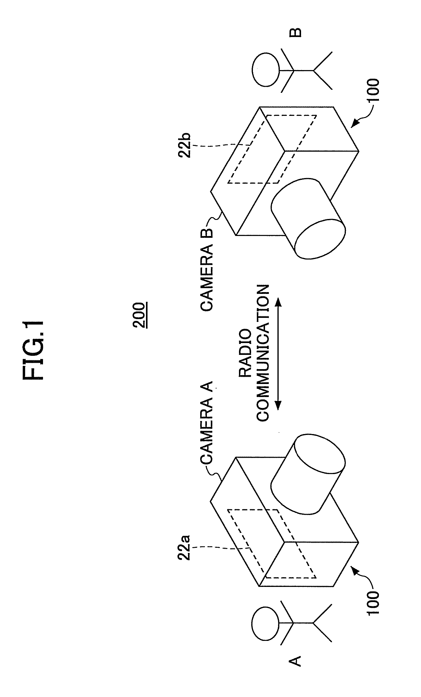
[0074]FIG. 1 is an illustration of a camera system provided with two cameras. Each of the digital cameras 100 displays a code image of arbitrary information on a monitor display part 22. The code image displayed by one of the digital cameras 100 is image-taken by the other of the digital cameras 100 so that the other of the digital cameras 100 decodes the code image to acquire the arbitrary information represented by the code image.

[0075]Hereinafter, one of the two digital cameras 100 is referred to as a camera A, and the other of the digital cameras 100 is referred to as a camera B. Similarly, a suffix “a” represents a function of the camera A, and a suffix “b” represents a function of the camera B. Although it is assumed that a user B of the camera B desires to communicate with the camera A in the following description, a user A of the camera A may desire to communicate...


PUM


Abstract

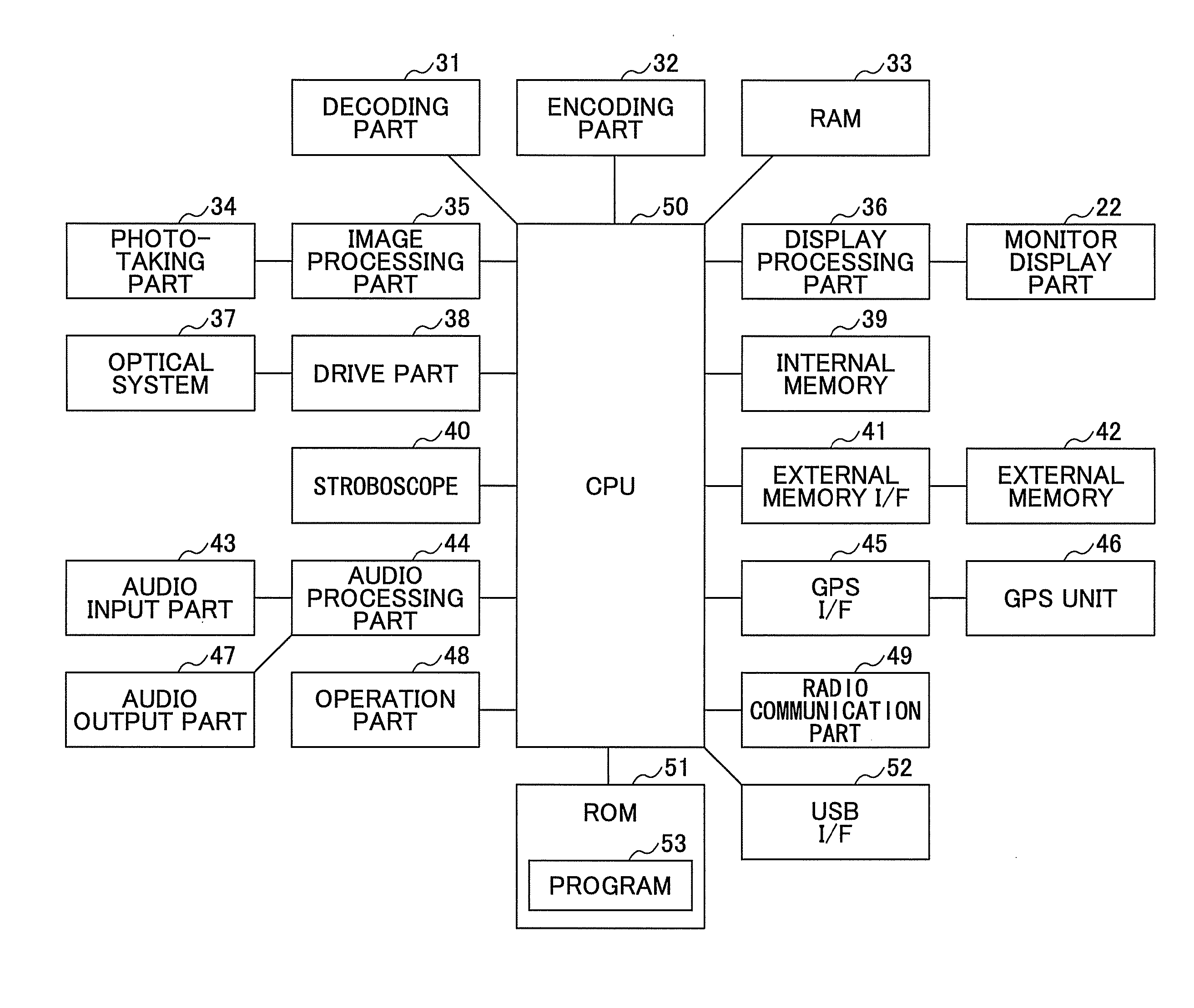
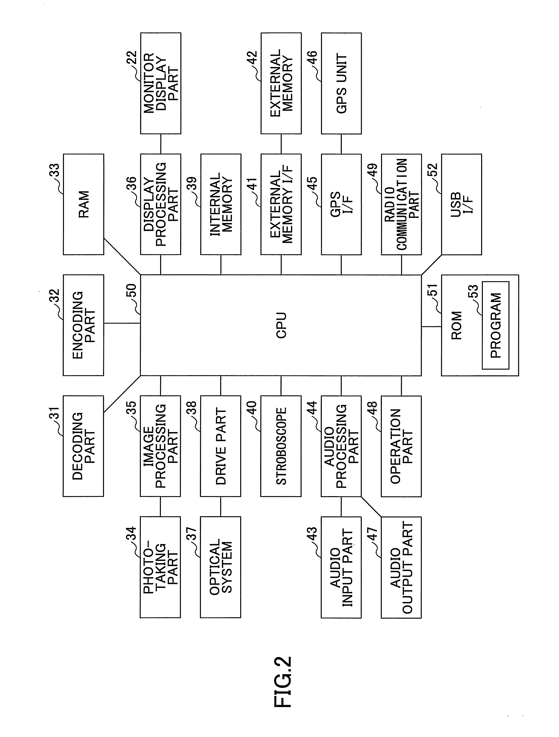
In a photographing apparatus, an encoding part creates a code image from authentication information of the photographing apparatus. A photographing part takes a photograph of a connection code image displayed on a display part of another apparatus. A decoding part decodes the connection code image contained in the photograph taken by the photographing part to decode encoded connection information containing communication setup information, which has been encoded according to the authentication information of the photographing apparatus. A restoration part restores the communication setup information from the encoded connection information by using the authentication information of the photographing apparatus. A radio communication part communicates with the another apparatus by using the communication setup information restored by the restoration part.

Description

BACKGROUND OF THE INVENTION[0001]1. Field of the Invention[0002]The present invention relates to a photographing apparatus such as a digital camera and, more particularly, to a photographing apparatus that is radio-communicable with other photographing apparatuses.[0003]2. Description of the Related Art[0004]Digital cameras have become widely used in recent years, and a method of using a digital camera has become diversified. For example, some digital cameras are provided with a radio LAN function, which enables radio communication between digital cameras to exchange data of images taken by the digital cameras of each other. Japanese Laid-Open Patent Application No. 2007-142681 suggests a technique to send an IP address or a MAC address to a remote apparatus. Disclosed in this patent document is a communication method in which a digital camera stores an image of an encoded IP address or MAC address of the digital camera and another digital camera takes an image of the displayed enco...

Claims


Application Information

Patent Timeline
IPC IPC(8): H04N5/232G03B17/00H04N5/225H04W12/02
CPCG06F21/36H04L2209/80G06F2221/2119H04L63/0861H04N1/00347H04N1/00408H04N1/00427H04N1/0044H04N1/00472H04N1/00474H04N1/00962H04N1/00973H04N1/2112H04N1/4406H04N1/4433H04N5/23203H04N5/23206H04N5/23216H04N5/23293H04N2101/00H04N2201/0041H04N2201/0055H04N2201/0084H04N2201/3236H04N2201/3269H04N2201/3273H04L9/3226G06F2221/2111H04N23/66H04N23/661H04N23/62H04N23/631H04N23/635
Inventor ASANO, TAIGA
Owner RICOH KK
Learn More