
Shutter drive unit and three dimensional image display system

a drive unit and display system technology, applied in the field of shutter drive units and three-dimensional image display systems, can solve the problems of large consumption, reduced power consumption, and inability to obtain sufficient operating time with small batteries, and achieve the effect of reducing power consumption and sufficient operating tim

Inactive Publication Date: 2011-03-03
SATURN LICENSING LLC
View PDF2 Cites 5 Cited by
  • Summary
  • Abstract
  • Description
  • Claims
  • Application Information

AI Technical Summary

Benefits of technology

[0022]In the liquid crystal shutter drive unit for the 3D eyeglasses, the low power consumption drive is the essential item in order to enable a long-time continuous operation to be carried out with a small battery.
[0024]The present invention is made in order to solve the problems described above, and it is therefore desirable to provide a shutter drive unit in which it is possible to reduce power consumption, and even with a drive by a small battery, a sufficient operating time can be obtained for 3D eyeglasses, and a 3D image display system including the same.
[0054]As set forth hereinabove, according to the embodiments of the present invention, it is possible to reduce the power consumption, and thus with the drive by the small battery, the sufficient operating time can be obtained for the 3D eyeglasses.

Problems solved by technology

Therefore, the power consumption is large, and thus it is feared that it is difficult to reduce the power consumption and thus a sufficient operating time cannot be obtained with the small battery.

Method used


Image

  • Shutter drive unit and three dimensional image display system
  • Shutter drive unit and three dimensional image display system
  • Shutter drive unit and three dimensional image display system

Examples


first embodiment

1. First Embodiment

[0072]FIG. 3 is a view showing an outline of an exterior appearance of a three-dimensional image display system according to a first embodiment of the present invention.

[0073]FIG. 4 is a block diagram showing a configuration of the three-dimensional image display system according to the first embodiment of the present invention.

[0074]This three-dimensional (3D) image display system 10 is composed of an image display apparatus 20 and a 3D eyeglass main body 30.

[0075]The image display apparatus 20 includes a display device 21 and a communication portion 22.

[0076]The display device 21, for example, is composed of a liquid crystal television (TV) apparatus and the like, and displays thereon an image which is stereoscopically viewed so as to follow the drive for the 3D eyeglass main body 30.

[0077]The communication portion 22 has a function of transmitting a synchronous signal or the like for image display, and receiving information from the 3D eyeglass main body 30 in ...

second embodiment

2. Second Embodiment

[0096]FIG. 5 is a circuit diagram showing a configuration of a shutter drive unit according to a second embodiment of the present invention.

[0097]The shutter drive unit 100 shown in FIG. 5 has a first inductor L101, a second inductor L102, a first drive path P101 connected to one end of the first inductor L101, and a second drive path P102 connected to one end of the second inductor L102.

[0098]The shutter drive unit 100 has a first drive object capacitive load LC101 included in the LC shutter 35R as the first shutter, and a second drive object capacitive load LC102 included in the LC shutter 35L as the second shutter.

[0099]The shutter drive unit 100 has a first clamping circuit 101, a second clamping circuit 102, a first switch 103, and a second switch 104.

[0100]The shutter drive unit 100 has a power source 105 as a power collection capacitance portion in which the other end sides of the first inductor L101 and the second inductor L102 are commonly connected to e...

third embodiment

3. Third Embodiment

[0225]FIG. 8 is a circuit diagram showing a configuration of a shutter drive unit according to a third embodiment of the present invention.

[0226]FIG. 9 is a timing chart explaining an operation of the shutter drive unit according to the third embodiment of the present invention.

[0227]The shutter drive unit 100A according to the third embodiment of the present invention is different from the shutter drive unit 100 according to the second embodiment of the present invention in that the inductor is shared between the drive object capacitive loads.

[0228]Referring to FIG. 8, the first drive path P101 and the second drive path P102 are each connected to one end side of the inductor L101.

[0229]In addition, in the shutter drive unit 100A of the third embodiment, diodes each serving as an ESD (Electrostatic Discharge) protecting element are connected between each of the first drive path P101 and the second drive path P102, and the power source potential Vdd, and between ea...


PUM


Abstract

Disclosed herein is a shutter drive unit, including: at least one inductor; first and second drive paths; first and second shutter including first and second drive object capacitive loads, respectively; first and second clamping circuits adapted to clamp the first and second drive object capacitive loads either to a power source potential or to a reference potential through the first and second drive paths, respectively; a first switch adapted to switch connection and non-connection between the inductor and the first drive object capacitive load over to each other; a second switch adapted to switch connection and non-connection between the inductor and the second drive object capacitive load over to each other; and a power collecting portion having a function of applying an intermediate voltage between the power source potential and the reference potential to the inductor, and a power collecting function of collecting a power by the inductor.

Description

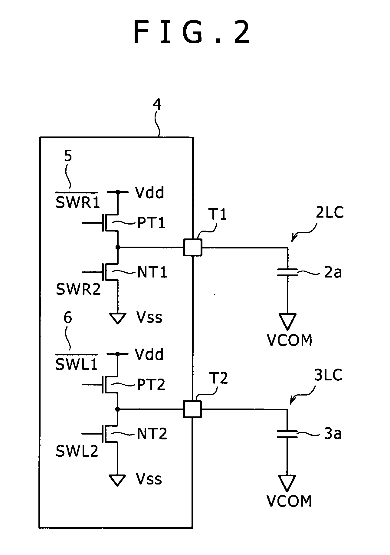
BACKGROUND OF THE INVENTION[0001]1. Field of the Invention[0002]The present invention relates to a shutter drive unit for causing a three-dimensional (3D) stereoscopic image to be expressed by driving shutters of 3D eyeglasses, and a 3D image display system including the same.[0003]2. Description of the Related Art[0004]FIG. 1 is a view showing a concept of 3D eyeglasses.[0005]As shown in FIG. 1, in 3D eyeglasses 1, liquid crystal shutters 2 and 3 are disposed in portions corresponding to right and left lenses of general eyeglasses, respectively.[0006]Also, the liquid crystal (LC) shutters 2 and 3 are turned ON or OFF synchronously with image display by a shutter drive unit, thereby expressing a 3D stereoscopic image.[0007]FIG. 2 is a circuit diagram showing a configuration of a general shutter drive unit.[0008]A shutter drive unit 4 is integrated in the form of a driver IC (Integrated Circuit).[0009]The shutter drive unit 4 includes a driver 5, a driver 6, a drive terminal T1 for t...

Claims


Application Information

Patent Timeline
Patent Type & Authority Applications(United States)
IPC IPC(8): H04N13/04H03K3/00G02B30/25
CPCH03K19/0019H03K19/0948H04N2213/008H04N13/0497H04N13/0438H04N13/341H04N13/398G09G3/003G09G3/2965G02B30/00G02B30/24G02B30/25H04N5/30
Inventor SHIGYO, NOBUHIKOSUZUKI, TOSHIOHASHIKAKI, KOICHISAKAI, SEIGOU
Owner SATURN LICENSING LLC
Learn More