Reconfigurable device

Inactive Publication Date: 2011-02-24
FUJIFILM BUSINESS INNOVATION CORP
View PDF6 Cites 7 Cited by
  • Summary
  • Abstract
  • Description
  • Claims
  • Application Information

AI Technical Summary

Benefits of technology

[0008]With this command transmitting system, a command is transmitted from the command outputting unit to each processing element after a predetermined (fixed) delay. Accordingly, although at least a few clock cycles will be consumed to transmit a command, it is possible to unambiguously set the number of clock cycles (i.e., latency) required to transmit the command. This means that it is possible to transmit a command synchronously to all of the processing elements included in the reconfigurable section, not just the processing elements in each respective section. Accordingly, even when a data flow is configured from a large number of processing elements, by outputting commands with consideration to the predetermined latency, it is possible to temporarily stop (halt) and reactivate (resume) the large number of processing elements that construct the data flow in synchronization.
[0013]In this device, a command is transmitted via the command collecting system and the command transmitting system even to processing elements in the same segment to which the processing element that generated the command belongs. In addition, even the processing element that generated the command itself receives the command via the command collecting system and the command transmitting system. Accordingly, for all of the processing elements that belong to the reconfigurable section, the latency from the generation of a command in a processing element until the command is received in the processing element is uniform. This means that it is possible to transmit the command to all of the processing elements that belong to a data flow reconfigured across a plurality of segments included in the reconfigurable section in synchronization, and thereby prevent inconsistencies in the processing by the data flow.
[0014]The command outputting unit is equipped with a function as a command relay unit that transmits a command outputted from the at least part of the processing elements via the second level command transmitting matrix to the plurality of transmission command registers. By providing a register (flip-flop) in the command outputting unit, it is possible to set the latency with which a command is transmitted to the respective processing elements with even higher precision. The at least part of processing elements that are the sources of commands can output a command taking the clock cycles required for transmitting the command by the command collecting system and the command transmitting system into account to appropriately control the data flow. The command outputting unit may be included in an output interface element.
[0016]The command generating unit included in an input interface element and / or a data storage-type element should preferably output a stop command when the amount of data remaining in the respective storage units has become equal to an amount of data consumed by the data flow that processes such data during the cycles (clock cycles, latency) consumed when transmitting the command using the command collecting system and the command transmitting system. When the input interface element or the data storage element provides data to the data flow, it is possible to temporarily stop the processing by such data flow to prevent inconsistencies from occurring and to then restart the processing by the data flow. When the final data is in the storage unit, the command generating unit should preferably be able to output the final data without outputting a stop command.
[0017]When a plurality of data flows are configured in the reconfigurable section, the plurality of processing elements included in the reconfigurable section should preferably each include a control unit that includes identification information that identifies the data flows to which the respective processing elements belong and for the command to include identification information. It is also possible to identify processing elements included in the plurality of data flows using the identification information, to stop only the data flows that should be stopped, and to allow other data flows to continue operating. It is also preferable for the identification information that identifies a data flow upstream from a processing element that includes a command generating unit to differ to the identification information that identifies a data flow downstream from the processing element. By controlling the operation of the data flow upstream from the processing element and the operation of the downstream data flow separately, it becomes possible to resolve the factors behind the generation of commands.

Problems solved by technology

When the number of processing units that can be used to reconfigure a data flow is several hundred or more, if control information or the like for temporarily stopping a data flow does not reach the respective processing units at the same timing, it will be difficult to temporarily stop the data flow without destroying the data being processed by the data flow or the processing state of the data flow.

Method used


Image

  • Reconfigurable device
  • Reconfigurable device
  • Reconfigurable device

Examples


Embodiment Construction

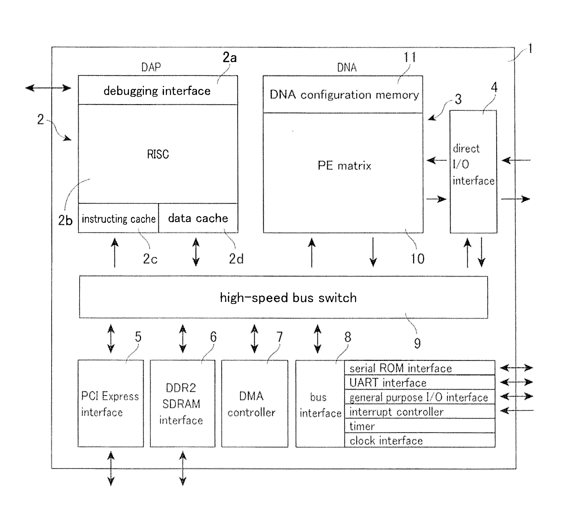
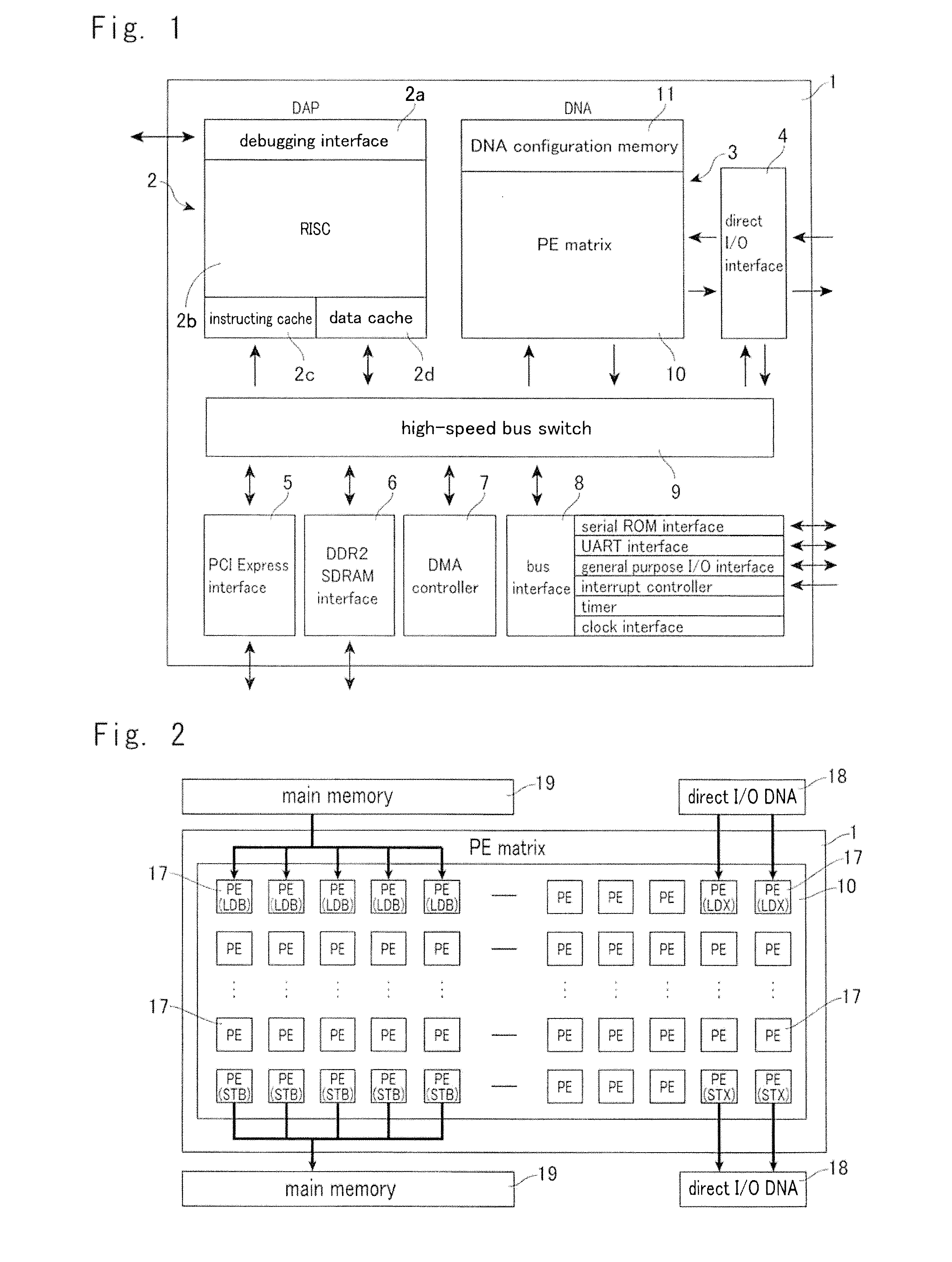
[0039]FIG. 1 shows one example of a reconfigurable device. This device 1 is a semiconductor integrated circuit device called a “DAPDNA” that was developed by the applicant of the present application. This device 1 includes a RISC core module 2 called a “DAP” and a Dynamic Reconfigurable Data-flow Accelerator 3 called a “DNA” (Distributed Network Architecture). In addition to the DAP 2 and the DNA 3, the device 1 includes an interface 4 for direct input and output into and out of the DNA 3, a PCI interface 5, SDRAM interface 6, a DMA controller 7, another bus interface 8 and a high-speed bus switch 9 for connecting such components. The DAP 2 includes a debugging interface 2a, a RISC core 2b, an instruction cache 2c, and a data cache 2d. The device (system) 1 is capable of being provided as a single chip (an IC, LSI, or ASIC), but alternatively may be provided as a chipset that includes a plurality of chips.

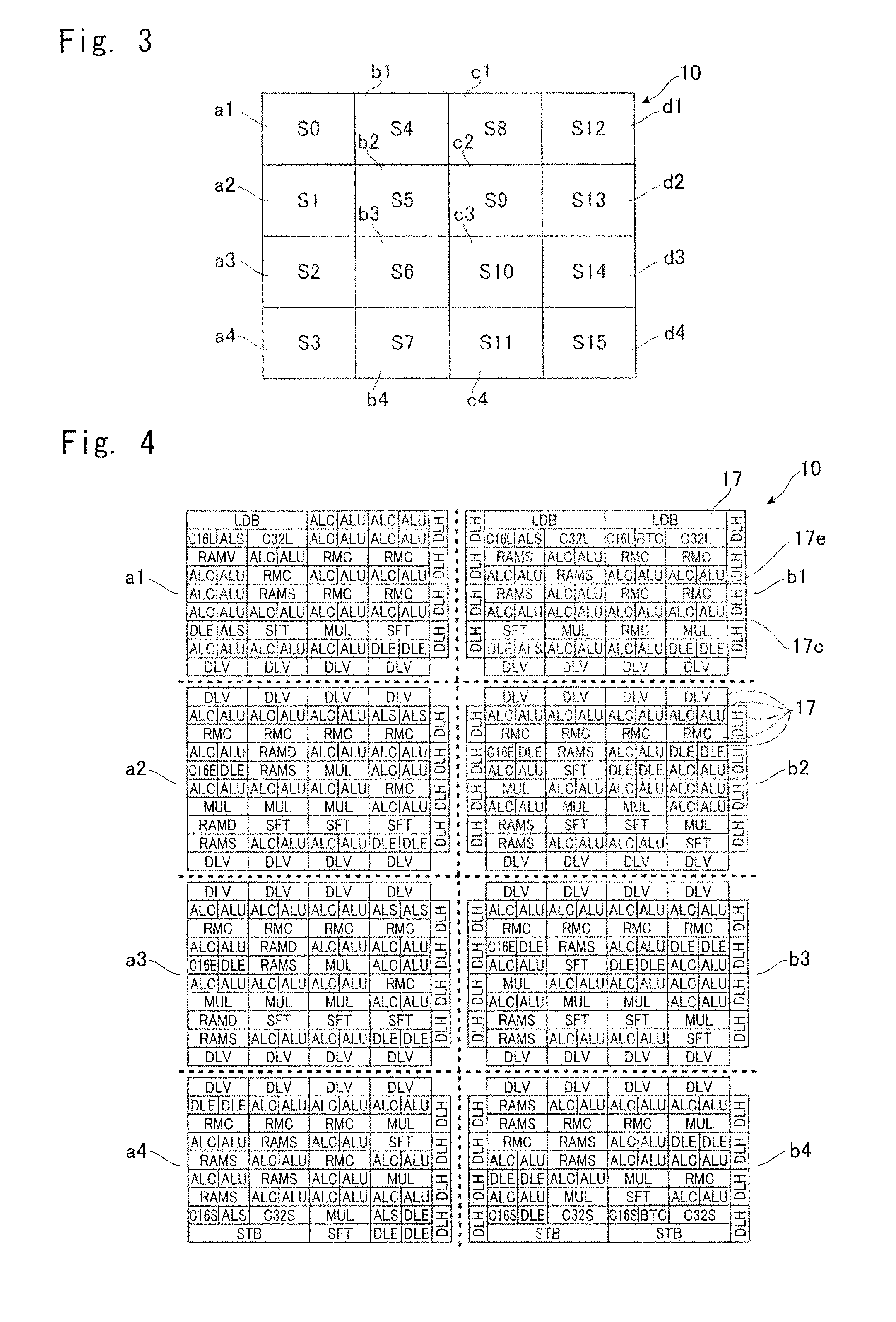
[0040]The DNA 3 includes a PE matrix (or simply “matrix”) 10 where 955 process...


PUM


Abstract

A device (1) including a reconfigurable section comprises a plurality of PEs (17) laid out having been divided into a plurality of segments and a command transmitting system (50) for transmitting commands to each PE (17). The command transmitting system (50) includes: a transmission command register (53) that is separately provided in each segment; a first level command transmitting matrix (51) for connecting the transmission command register (53) and PEs (17) in each segment with a delay of one clock; and a second level command transmitting matrix (52) for connecting the transmission command registers (53) of the plurality of segments and a command outputting unit (59) that outputs commands.

Description

TECHNICAL FIELD[0001]The present invention relates to a device in which circuits can be reconfigured.BACKGROUND ART[0002]International Patent Application WO2003 / 023602 discloses a data processing system that includes a plurality of processing units and is also equipped with first, second, and third data transferring means. The first data transferring means connects a plurality of processing units in a network and carries out handovers of first data. By connecting two or more of the processing units out of the plurality of processing units, at least one reconfigurable data flow is constructed. The second data transferring means supplies control information for loading setting data and other control information in parallel to a plurality of processing units as second data. The third data transferring means supplies setting data to individual units out of the plurality of processing units. The setting data includes data that configures different functional data flow by changing, direct...

Claims


Application Information

Patent Timeline
IPC IPC(8): G06F15/76G06F9/02
CPCG06F15/8007G06F15/7867
Inventor MATSUNO, HIROYUKI
Owner FUJIFILM BUSINESS INNOVATION CORP
Why Eureka
Try Eureka