Method of imaging for heart valve implant procedure

a heart valve and implant procedure technology, applied in the field of heart valve implant procedure imaging, can solve the problems of high risk, long recovery time or convalescence, damage to the heart valve,

Inactive Publication Date: 2011-02-24
SIEMENS AG
View PDF7 Cites 12 Cited by
  • Summary
  • Abstract
  • Description
  • Claims
  • Application Information

AI Technical Summary

Problems solved by technology

The heart valves can be damaged by other illnesses, for example by inflammation, influenza or cardiac infarction, to the extent that the valve must be replaced or surgically modeled.
Such procedures were associated with high risks and long recovery times or convalescence (up to six weeks or more) for the patient.
In principle, all four heart valves are accessible for a balloon dilation (referred to as valvuloplasty), but dilation of the tricuspid valve is only rarely implemented, due to the relative rarity of tricuspid stenosis.
This procedure is implemented under anesthesia, since filling of the balloon leads to a temporary interruption of circulation.
One problem with the aortic valve implantation is the risk of complications.
An additional problem is the high level of contrast agent that is used.
Relatively large quantities of contrast agent are necessary to perform such computer tomography imaging.
The disadvantage of CT is that the data acquisitions are typically performed a few days before the procedure and therefore do not reproduce the exact anatomy of the relevant area of the patient that may be present during the procedure.

Method used


Image

  • Method of imaging for heart valve implant procedure
  • Method of imaging for heart valve implant procedure
  • Method of imaging for heart valve implant procedure

Examples


Embodiment Construction

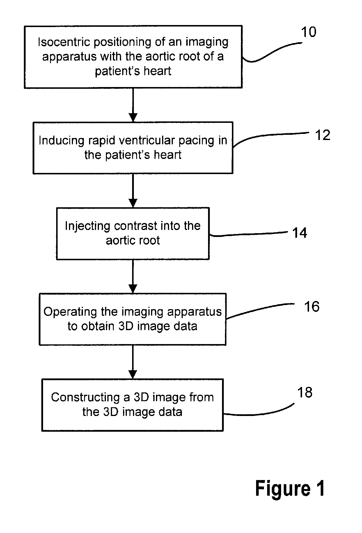
[0031]The invention provides a method of imaging so as to produce images to be displayed on a display device for use in an artificial heart valve implant procedure as shown in FIG. 1. The method includes the step, as shown at block 10, of isocentric positioning of the imaging system, such as the Siemens Dyna CT imaging system or other imaging system, with the aortic root of the patient's heart. The aortic root is the portion of the aorta that attaches to the heart and which contains the aortic valve.

[0032]After centering the aortic root relative to the imaging system's projection direction, rapid ventricular pacing of the patient's heart is triggered, or induced, in the patient, at step 12. The patient is also requested to hold their breath, or otherwise caused to temporarily stop breathing, such as if under control of a ventilator of the patient is under anaesthesia. The combination of rapid ventricular pacing and breath-hold reduces movement of the organs in the patient.

[0033]Duri...


PUM

PropertyMeasurementUnit
articulated imaging apparatusaaaaaaaaaa
magnetic resonance imagingaaaaaaaaaa
computed tomography imagingaaaaaaaaaa

Abstract

A method as a workflow for imaging for a heart valve implant procedure includes positioning the patient and an articulated imaging apparatus relative to one another, inducing rapid ventricular pacing in the patient, and imaging a region of the patient's heart to obtain image date for a three-dimensional image. The three-dimensional data is used to construct a three-dimensional image of the region of the patient's heart an the three-dimensional image is displayed for use in the implanting of the replacement heart valve. Optional steps may include obtaining a real time two-dimensional image of the patient's heart and superimposing the real time two-dimensional image with the constructed three dimensional image. The replacement valve is moved into position in the patient's heart during rapid ventricular pacing and breath hold using the superimposed two-dimensional and three-dimensional image information.

Description

BACKGROUND OF THE INVENTION[0001]1. Field of the Invention[0002]The present invention relates generally to a method of imaging a patient's heart for implant of an artificial heart valve into the heart, and in particular to a method of medical imaging as part of a heart valve implant procedure.[0003]2. Description of the Related Art[0004]The reduction of the pumping power of one or both heart chambers is generally referred to as a cardiac insufficiency. Cardiac insufficiency is not an actual illness, but rather is the result of various diseases and / or pathology symptoms. As a result of cardiac insufficiency, the body and its organs do not receive the necessary amount of blood per unit of time. The vital organs are supplied with only an insufficient quantity of oxygen and nutrients. Among the most important causes of cardiac insufficiency are illness of the coronary vessels (often the cause of extended infarctions), hypertension that is insufficiently medically regulated, heart muscle...

Claims


Application Information

Patent Timeline
Patent Type & Authority Applications(United States)
IPC IPC(8): A61F2/24A61B6/03A61B6/00G01N23/04H05G1/60G06K9/00G09G5/00
CPCA61B6/032A61F2/24A61B8/0883A61B6/503
Inventor NOETTLING, ALOISBOESE, JANJOHN, MATTHIASFALK, VOLKMARWALTHER, THOMAS
Owner SIEMENS AG
Why Eureka
Try Eureka