
Wearing article

a technology of articles and diapers, applied in the field of wearing articles, can solve the problems of inability to produce offensive sound, and achieve the effects of reducing manufacturing costs, reducing tensile force, and minimizing sound generated in the course of diapering or exchanging diapers

Inactive Publication Date: 2011-02-24
UNI CHARM CORP
View PDF9 Cites 15 Cited by
  • Summary
  • Abstract
  • Description
  • Claims
  • Application Information

AI Technical Summary

Benefits of technology

[0016]The fastening means comprise the hook elements provided on one of the front and rear waist regions and the target fibrous nonwoven fabric provided on the other of the front and rear waist regions and adapted to be detachably engaged with the hook elements to connect the front and rear waist regions with each other. With such arrangement, the sound generated in the course of putting or exchanging the diaper on or from the wearer's body can be minimized. Inboard of the hook elements as viewed in the transverse direction, there are provided the contractible regions adapted to be elastically contractible in the transverse direction so that the shear force generated from the tensile stress thereof may reinforce the engagement between the hook elements and the target nonwoven fabric. With the engagement reinforced in this manner, the target nonwoven fabric is not limited to a particular type of nonwoven fabric but various types of nonwoven fabric may be selectively employed as the target nonwoven fabric.
[0017]The chassis comprises the inner sheet defining the skin-facing side and the outer sheet defining the garment-facing side. The outer sheet is formed of the target fibrous nonwoven fabric and the article can be produced without any loop elements. Therefore, the manufacturing cost can be correspondingly reduced.
[0018]The non-contractible regions having none of elastic members are formed inboard of the respective contractible regions as viewed in the transverse direction. When the diaper is pulled in opposite directions with the hook elements or the regions in vicinities thereof gripped by the fingers, the above-described arrangement allows the pull force to be transmitted to the chassis as a whole by the intermediary of the non-contractible regions and therefore the position of the wearing article on the wearer's body can be adjusted with the hook elements or the regions in vicinities thereof gripped by the fingers.
[0019]The target fibrous nonwoven fabric comprises component fibers oriented in the longitudinal direction. The hook elements deeply bite into the target nonwoven fabric as the contractile force of the stretchable regions acting to pull the hook elements which have already been put in engagement with the target nonwoven fabric in the transverse direction is exerted to the hook elements. In this way, these hook elements and the target nonwoven fabric can be further firmly engaged together.
[0020]The chassis includes the leg-surrounding elastic members attached under tension along the side edges to extend in the longitudinal direction and the contractible regions cooperate with the leg-surrounding members as the diaper is put on the wearer's body to form the annular peripheral edges of the respective leg-openings. In other words, the leg-openings' peripheral edges can be defined by the leg-surrounding elastic members and the contractible regions so that the peripheral edges of the respective leg-openings may smoothly follow movement of the wearer's body and thereby alleviate tensile force in the shearing direction exerted on the fastening means.
[0021]The contractible regions include a plurality of elastic members or elastic nonwoven fabric ribbons, attached under tension to the contractible regions to be spaced one from another in the longitudinal direction and to extend in the transverse direction. With such arrangement, the portions defined between each pair of the adjacent elastic members or the elastic nonwoven fabric ribbons assure the air-permeability and the flexibility. It should be noted that use of the elastic members is more preferable than use of the elastic nonwoven fabric ribbons from the viewpoint of durability and manufacturing cost.

Problems solved by technology

More specifically, when the engagement of the hook elements with the loop elements is used, rather offensive sound is inevitably generated when the hook elements are disengaged from the loop elements.

Method used


Image

  • Wearing article
  • Wearing article
  • Wearing article

Examples


first embodiment

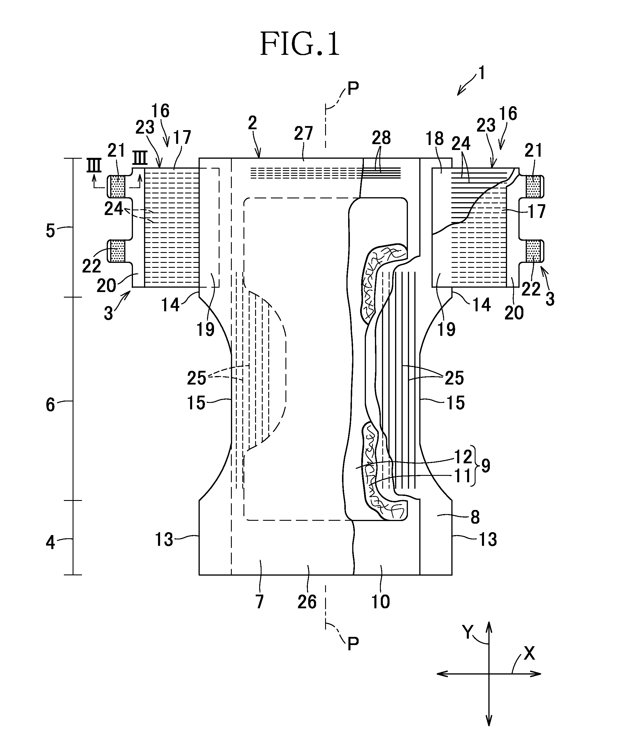
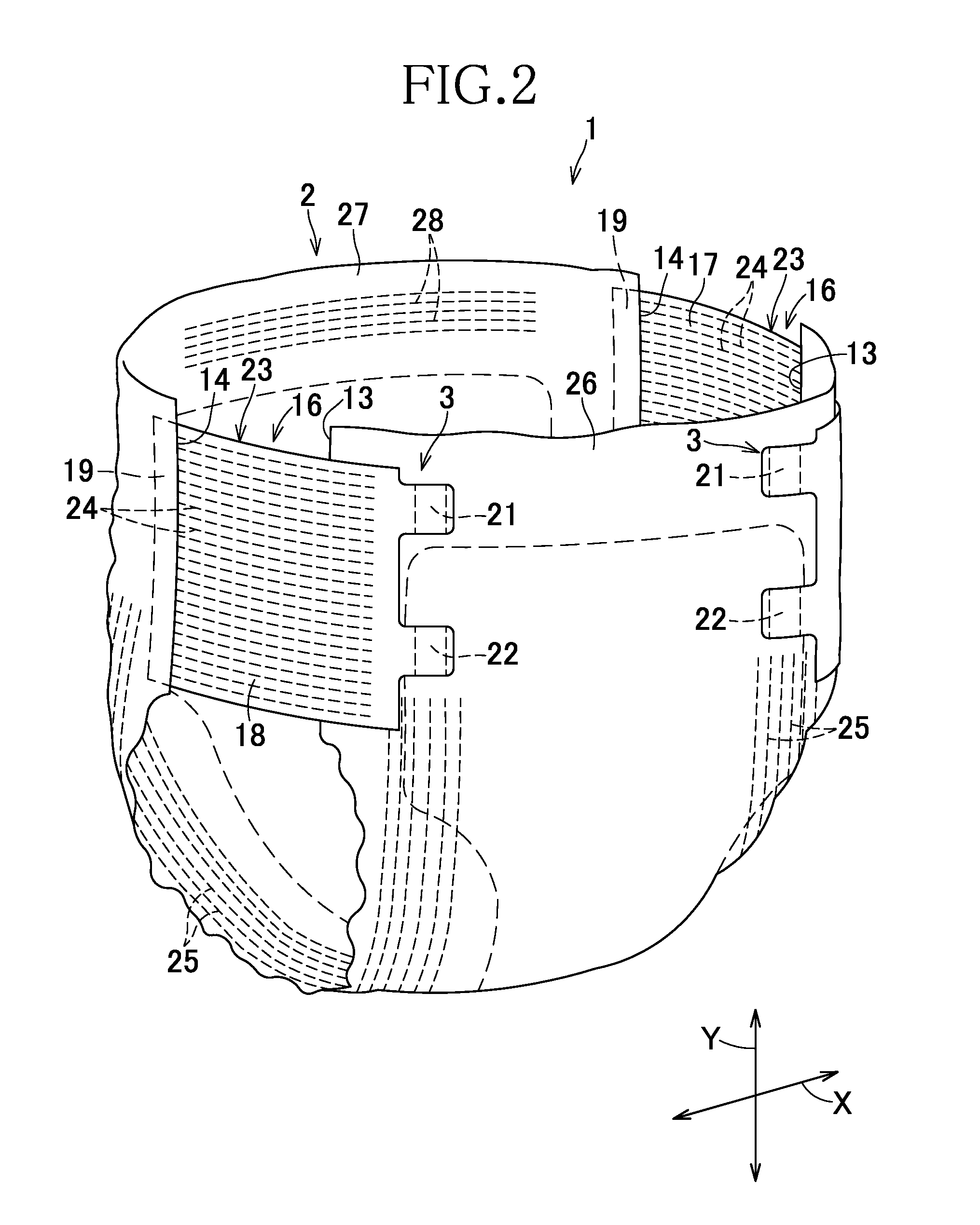
[0044]FIGS. 1 through 4 illustrate the first embodiment of the present invention. FIG. 1 is a plan view showing so-called open-type disposable diaper as partially cutaway for convenience of illustration. The diaper 1 comprises a liquid-absorbent chassis 2 and fastening means 3 attached to the chassis 2. The chassis 2 has front and rear waist regions 4, 5 and a crotch region 6 extending between these front and rear waist regions 4, 5. This chassis 2 comprises an inner sheet 7 defining the skin-facing side, an outer sheet 8 defining the garment-facing side, a liquid-absorbent structure 9 sandwiched between these inner and outer sheets 9 and a leak-barrier sheet 10 sandwiched between the liquid-absorbent structure 9 and the outer sheet 8.

[0045]The inner sheet 7 may be formed, for example, by an air-permeable nonwoven fabric. The liquid-absorbent structure 9 comprises a core 11 formed, for example, by mixture of fluff pulp and super-absorptive polymer particles and tissue paper 12 wrapp...

second embodiment

[0076]FIG. 6 shows a second embodiment of the present invention.

[0077]One of the features in the second embodiment is leak-barrier cuffs 29 provided on the skin-facing side of the inner sheet 7. Another feature is locations at which the flaps' elastic members 24 are attached to the diaper. The features other than these two features are similar to those in the first embodiment and these similar features will not be repetitively described.

[0078]The leak-barrier cuffs 29 extending between the front and rear ends 26, 27 of the chassis 2 in the longitudinal direction Y, shaped symmetrically about the longitudinal center line P-P and opposed to each other in the transverse direction X. Each of the leak-barrier cuffs 29 has inner and outer side edges 30, 31 opposed to each other in the transverse direction X and extending in the longitudinal direction Y and front and rear ends 32, 33 opposed to each other in the longitudinal direction Y and extending in the transverse direction X. The oute...


PUM


Abstract

The present invention aims to provide a wearing article improved so that various types of nonwoven fabrics can be effectively used for target nonwoven fabric without anxiety that the target nonwoven fabric once engaged with hook elements might be readily torn. As an outer sheet 8 defining a garment-facing side of a chassis 2, a commonly-used nonwoven fabric is used and this nonwoven fabric is oriented in a longitudinal direction Y. Rear waist region's side edges 14 of the chassis 2 are provided with flaps 16 attached thereto. Each of the flaps 16 has a joint region 19 along which the flap 16 is joined to the chassis 2 and first and second hook elements 21, 22. Between the joint region 19 and the first and second hook elements 21, 22 as viewed in the transverse direction X, a contractible region 23 adapted to be contractible in the transverse direction X. The contractible region 23 is provided with a plurality of flap's elastic members 24. The joint region 19 provided with none of the flap's elastic members 24 define a non-contractible region. The first and second hook elements 21, 22 of the flap 16 may be put in engagement with the outer sheet 8 to connect the front and rear waist regions 4, 5 to each other in a circumferential direction.

Description

TECHNICAL FIELD[0001]The present invention relates to wearing articles and more particularly to wearing articles such as disposable diapers, toilet-training pants or incontinent briefs.RELATED ART[0002]Disposable diapers adapted to be handled for actual use so that front and rear waist regions maybe joined together to form so-called pant-type diaper is known, for example, from JP 2003-180748 A (PATENT DOCUMENT 1). According to the disclosure of this PATENT DOCUMENT 1, the diaper comprises front and rear waist regions and a chassis has a skin-facing side and a garment-facing side. The chassis has an inner sheet defining the skin-facing side and an outer sheet defining the garment-facing side wherein the outer sheet is formed of an air-through fibrous nonwoven fabric and the inner sheet of the rear waist region is provided with hook elements. The hook elements maybe put in engagement with the outer sheet of the front waist region to join the front and rear waist region together and th...

Claims


Application Information

Patent Timeline
Patent Type & Authority Applications(United States)
IPC IPC(8): A61F13/49A61F13/62
CPCA61F13/49015A61F13/5622A61F13/62A61F13/51476A61F13/5148A61F13/5638A61F13/5644A61F13/622
Inventor MIZUTANI, KATSUMITODA, HARUKISUZUKI, MAIKOTANAKA, YOSHIKAZU
Owner UNI CHARM CORP
Learn More