
Synthesis reaction system for hydrocarbon compound, and method of removing powdered catalyst particles

a synthesis reaction and hydrocarbon compound technology, applied in the direction of moving filter element filters, separation processes, filtration separation, etc., can solve the problems of deterioration of the catalyst used in the step or the deterioration of liquid fuel products, and the particle diameter of the catalyst particles included in the slurry may become gradually small, so as to prevent the loss of hydrocarbon compound weight, the filter cleaning timing is determined accurately, and the effect of reducing the loss of hydrocarbon compound

Active Publication Date: 2011-02-24
NIPPON STEEL & SUMIKIN ENG CO LTD +5
View PDF11 Cites 13 Cited by
  • Summary
  • Abstract
  • Description
  • Claims
  • Application Information

AI Technical Summary

Benefits of technology

[0007]The present invention has been made in view of such problems, and aims at providing a method of removing powdered particles which is suitable to prevent powdered particles from flowing into an upgrading section of liquid fuel products, thereby preventing any deterioration of the liquid fuel products, in the synthesis reaction system which carries out an FT synthesis reaction.[Means for Solving the Problem]

Problems solved by technology

However, the particle diameter of the catalyst particles included in the slurry may become gradually small due to friction between catalyst particles, the friction with an inner wall of the reactor main body, or the like, and any thermal damage by the FT synthesis reaction, that is, the catalyst particles are powdered gradually.
When the powdered particles flow into the upgrading section of liquid fuel products, there is a probability that deterioration of a catalyst to be used in the step or deterioration of the liquid fuel products may be caused.

Method used


Image

  • Synthesis reaction system for hydrocarbon compound, and method of removing powdered catalyst particles
  • Synthesis reaction system for hydrocarbon compound, and method of removing powdered catalyst particles
  • Synthesis reaction system for hydrocarbon compound, and method of removing powdered catalyst particles

Examples


Embodiment Construction

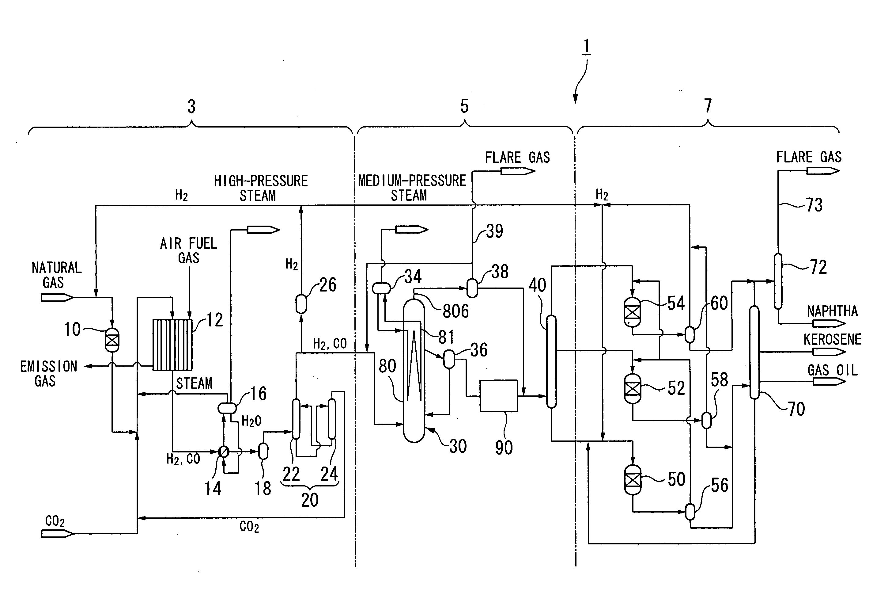
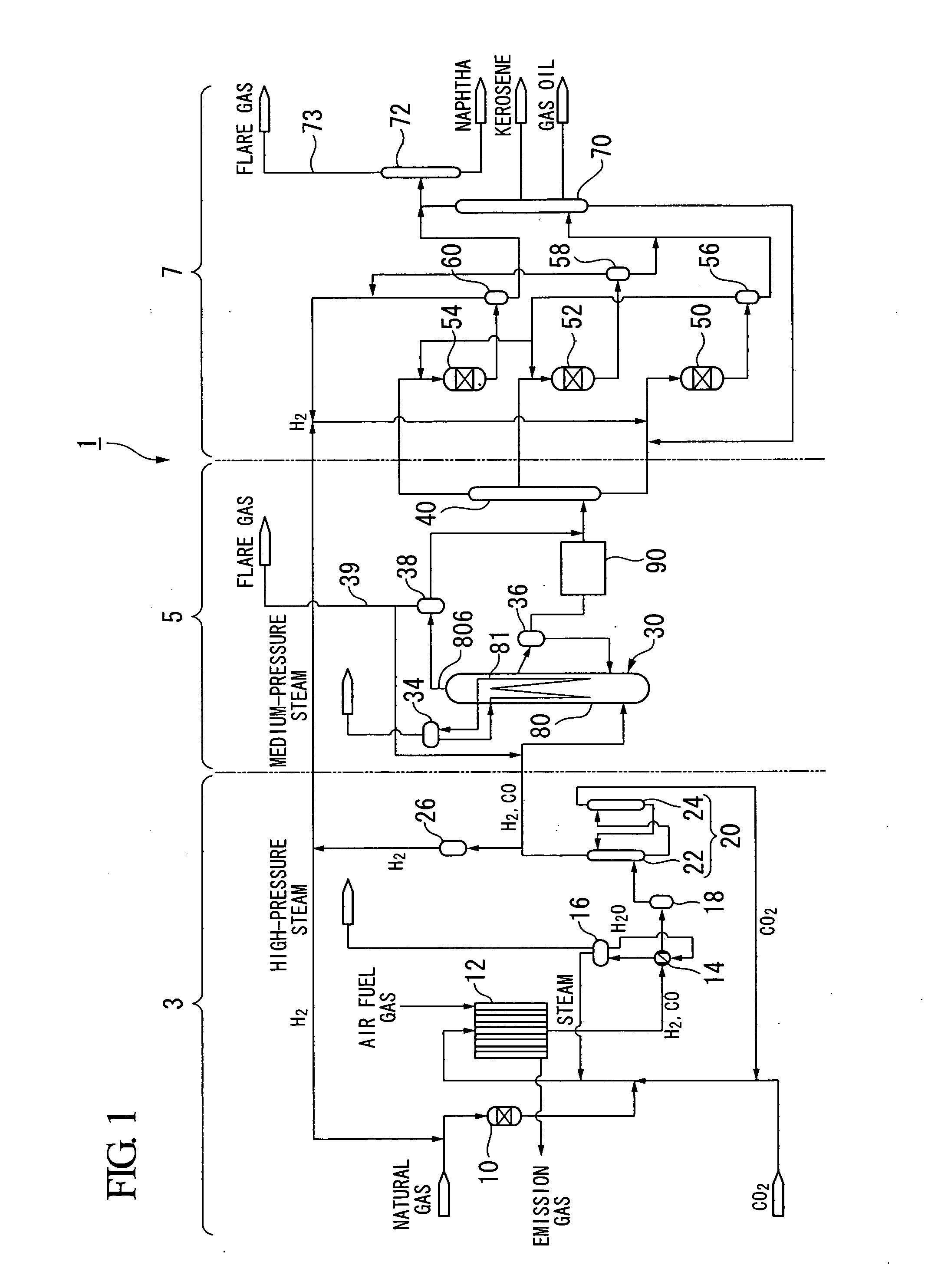
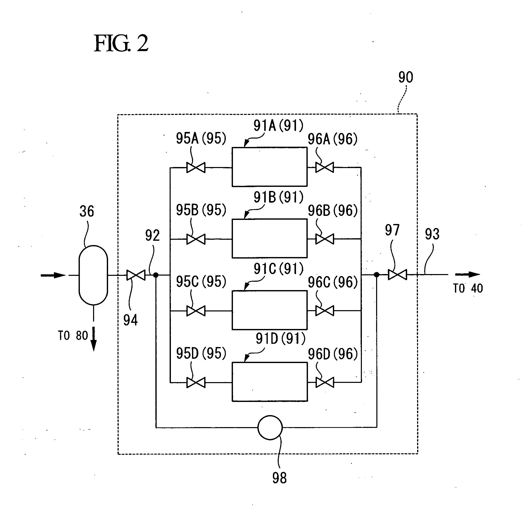
[0053]Hereinafter, preferred embodiments of the present invention will be described with reference to FIGS. 1 to 3.

[0054]As shown in FIG. 1, the liquid fuel synthesizing system (hydrocarbon synthesis reaction system) 1 according to the present embodiment is a plant facility which carries out the GTL process which converts a hydrocarbon raw material, such as natural gas, into liquid fuel. This liquid fuel synthesizing system 1 includes a synthesis gas production unit 3, an FT synthesis unit 5, and an upgrading unit 7. The synthesis gas production unit 3 reforms natural gas, which is a hydrocarbon raw material, to produce synthesis gas including carbon monoxide gas and hydrogen gas. The FT synthesis unit 5 produces liquid hydrocarbons from the produced synthesis gas by the Fischer-Tropsch synthesis reaction (hereafter referred to as “FT synthesis reaction”). The upgrading unit 7 hydrogenates and hydrocracks the liquid hydrocarbons produced by the FT synthesis reaction to produce liqui...


PUM

PropertyMeasurementUnit
diameteraaaaaaaaaa
diameteraaaaaaaaaa
mean particle diameteraaaaaaaaaa

Abstract

A synthesis reaction system is provided with: a reactor which synthesizes a hydrocarbon compound by a chemical reaction of a synthesis gas including hydrogen and carbon monoxide as main components, and a slurry having solid catalyst particles suspended in liquid; a separator which separates the hydrocarbon compound from the slurry; and a filtering device which filters the hydrocarbon compound extracted from the separator to trap powdered catalyst particles.

Description

TECHNICAL FIELD[0001]The present invention relates to a synthesis reaction system for a hydrocarbon compound which synthesizes the hydrocarbon compound by introducing a synthesis gas including carbon monoxide gas and hydrogen gas as main components into a slurry having solid catalyst particles suspended in liquid hydrocarbons, and a method of removing powdered catalyst particles, which removes catalyst particles (powdered particles) included in a hydrocarbon compound in a powdered state.[0002]Priority is claimed on Japanese Patent Application No. 2008-66154, filed Mar. 14, 2008, the content of which is incorporated herein by reference.BACKGROUND ART[0003]As synthesis reaction systems which synthesize hydrocarbon compounds by a Fischer-Tropsch synthesis reaction (hereinafter referred to as “FT synthesis reaction”) by using a synthesis gas mainly composed of carbon monoxide (CO) gas and hydrogen gas (H2) as a raw material gas, for example, like the PATENT DOCUMENT 1, there is a bubble...

Claims


Application Information

Patent Timeline
Patent Type & Authority Applications(United States)
IPC IPC(8): B01J8/00B01D37/00
CPCB01D39/10B01D2239/0668C10G2/342C10G2/32B01J2219/00006B01J8/00
Inventor ONISHI, YASUHIROKATO, YUZURUMURATA, ATSUSHIYAMADA, EIICHI
Owner NIPPON STEEL & SUMIKIN ENG CO LTD
Learn More