
Zoom lens barrel

a zoom lens and barrel technology, applied in the field of zoom lens barrels, can solve the problems of difficult adjustment of the desired focal length, and achieve the effects of easy and fine adjustment, enhanced operability, and enhanced view angl

Inactive Publication Date: 2011-02-24
CANON KK
View PDF5 Cites 0 Cited by
  • Summary
  • Abstract
  • Description
  • Claims
  • Application Information

AI Technical Summary

Benefits of technology

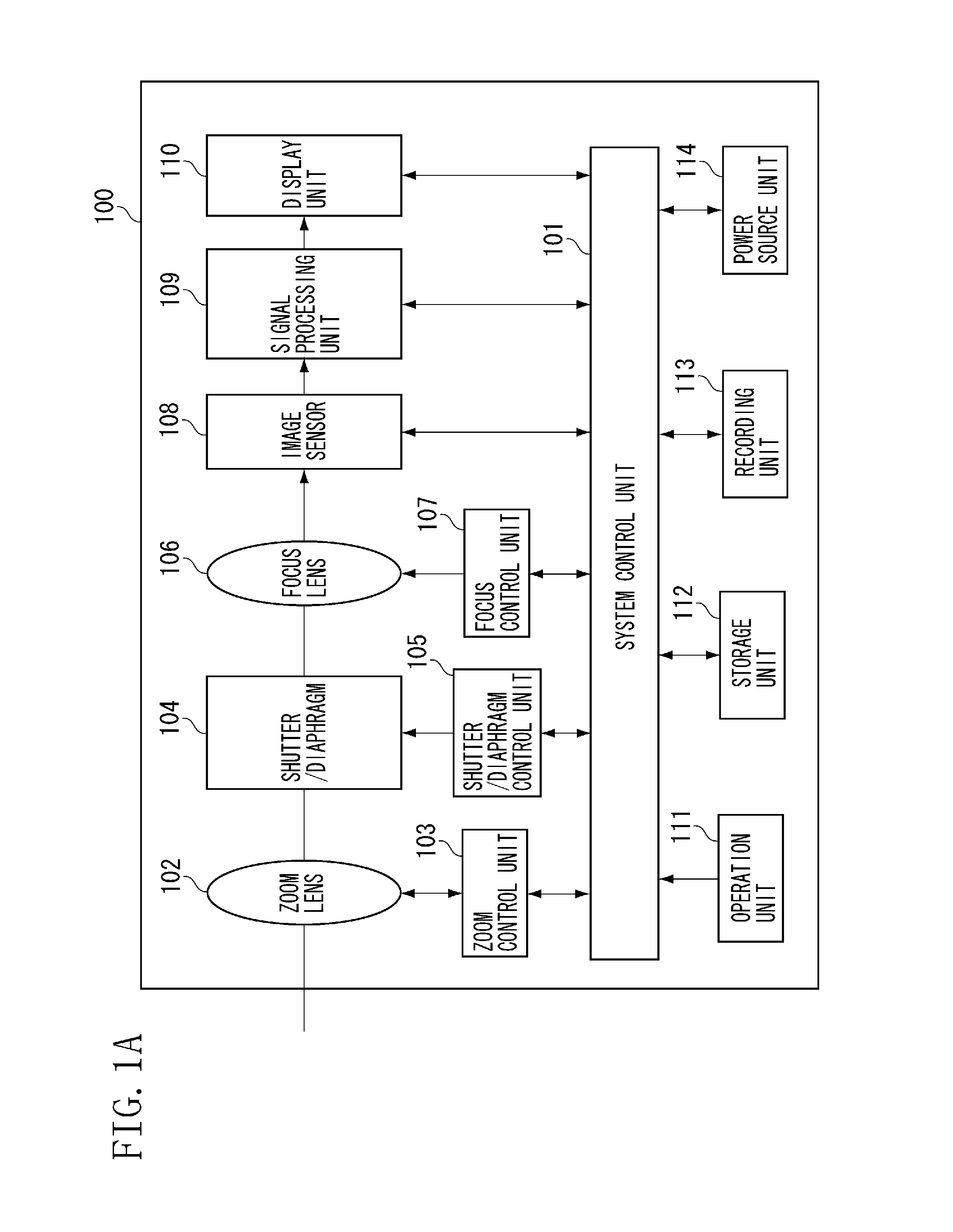
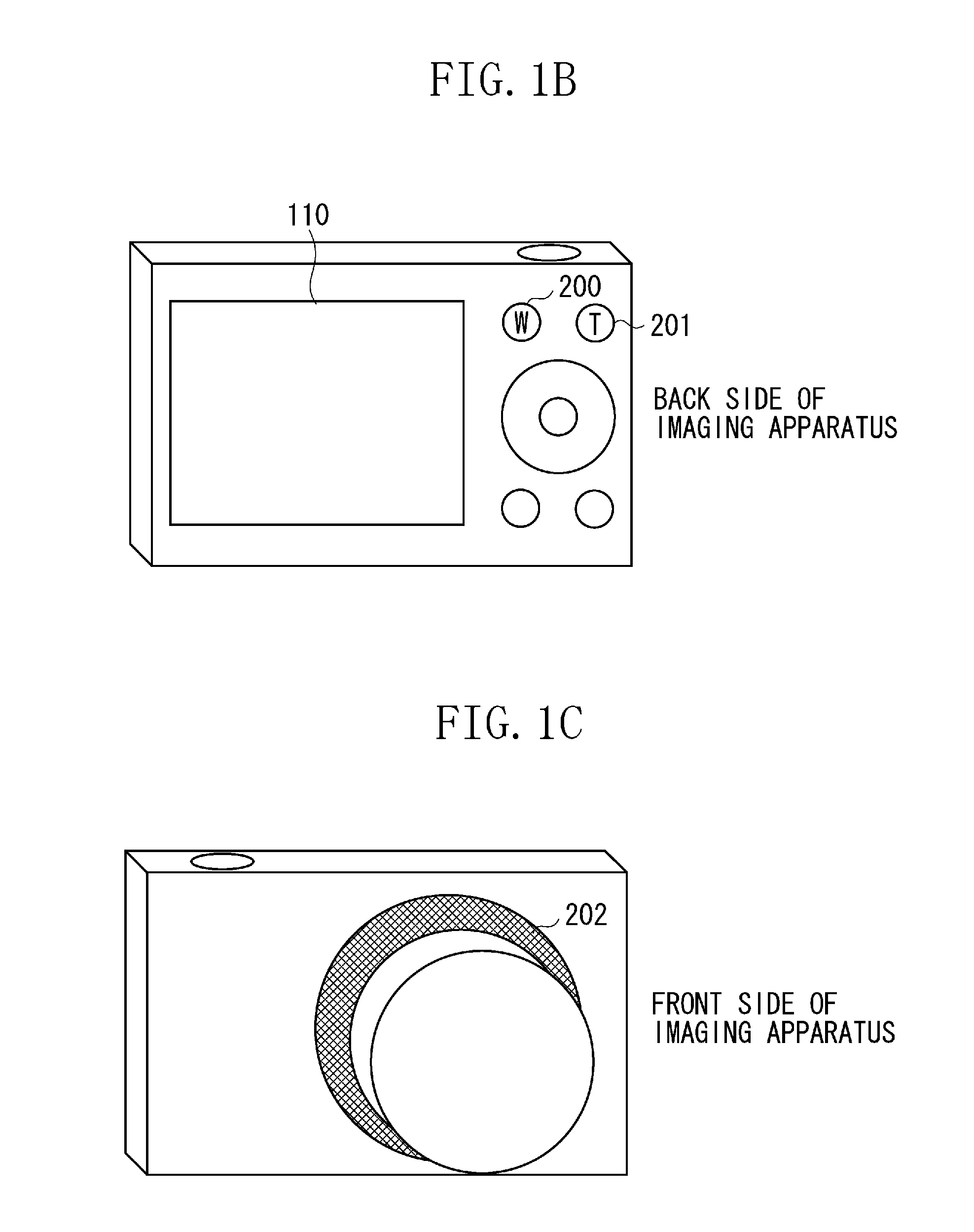
The present invention provides a lens control apparatus with a zoom lens that has two zoom control modes. This allows for easier and finer adjustment of the angle of view to a desired one. The apparatus includes first and second operation members that give a zoom instruction for moving the zoom lens, and a controller that changes the zoom stop position accordingly. The first mode changes the zoom stop position to a first pattern, while the second mode changes it to a second pattern with a wider interval. This results in a more intuitive and efficient way of adjusting the focal length and angle of view of the imaging apparatus.

Problems solved by technology

However, when a user intends to take a photo with the specific focal length such as 28 mm, 35 mm, or 50 mm, which is generally used for a short focal lens of a camera, the problem described below arises according to the technique discussed in Japanese Patent Application Laid-Open No. 2-68507.
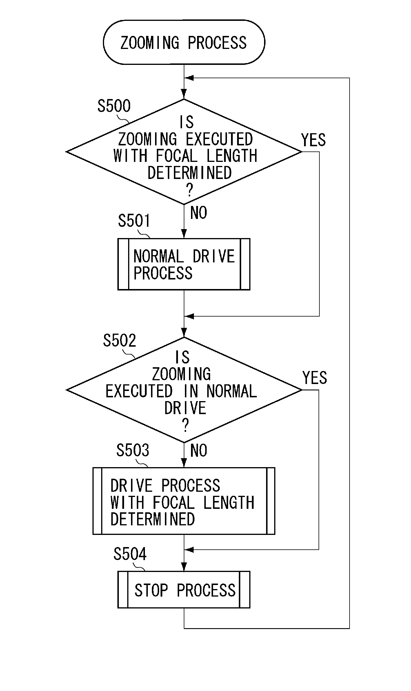
Namely, correctly adjusting the focal length to the desired one is not easy in the zoom mode that continuously changes the focal length.
Further, when the focal length, that is stepwisely changed, does not have a desired angle of view, and a user intends to perform fine adjustment, the user has to change the mode to the zoom mode that continuously changes the focal length, and then, the user has to perform again the zoom operation.

Method used


Image

  • Zoom lens barrel
  • Zoom lens barrel
  • Zoom lens barrel

Examples


Embodiment Construction

[0017]Various exemplary embodiments, features, and aspects of the invention will be described in detail below with reference to the drawings.

[0018]The present invention will now be described in detail below with reference to the accompanying drawings illustrating embodiments thereof.

[0019]An important point of the present invention is that the present invention includes the above first and second zoom control modes. Typically, the control mode can be changed to the first zoom control mode according to the operation of the first operation member, and the control mode can be changed to the second zoom control mode according to the operation of the second operation member. When the zooming is executed by the optical zooming in the zoom control mode, it can be determined from the viewpoint of the control position of the zoom lens that by the operation member, the zoom position can be changed in a first pattern or in a designated manner. When the zooming is executed by an electronic zoom...


PUM


Abstract

A lens control apparatus having a zoom lens includes first and second operation members that give a zoom instruction for moving the zoom lens, and a controller that changes a zoom stop position to a first pattern according to the operation of the first operation member, and changes the zoom stop position to a second pattern, which has an interval wider than that in the first pattern, according to the operation of the second operation member.

Description

BACKGROUND OF THE INVENTION[0001]1. Field of the Invention[0002]The present invention relates to an imaging apparatus, and more particularly to a technique of enhancing operability when a focal length or an angle of view of a captured image is changed in an imaging apparatus having a zoom function.[0003]2. Description of the Related Art[0004]Japanese Patent Application Laid-Open No. 2-68507 discusses that conventional imaging apparatuses having a zoom lens include the one in which a zoom mode continuously changes the focal length and the other in which a zoom mode stepwisely changes a predetermined focal length, when a focal length of the zoom lens is changed.[0005]However, when a user intends to take a photo with the specific focal length such as 28 mm, 35 mm, or 50 mm, which is generally used for a short focal lens of a camera, the problem described below arises according to the technique discussed in Japanese Patent Application Laid-Open No. 2-68507. Namely, correctly adjusting t...

Claims


Application Information

Patent Timeline
Patent Type & Authority Applications(United States)
IPC IPC(8): G02B15/14H04N23/40
CPCG02B15/14G02B7/09H04N5/23296H04N5/23203H04N23/66H04N23/69
Inventor MANIWA, JUNICHIYOSHINO, EIJISUDO, KOJIFUJITANI, YOHEI
Owner CANON KK
Learn More